Little Quadruped Has PCB Spine And No Wiring

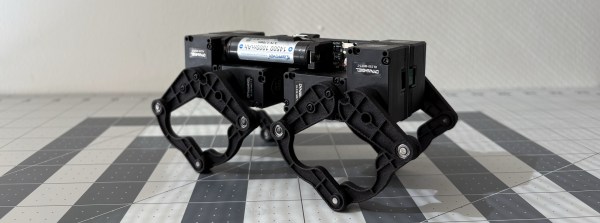
Dealing with all the wiring can quickly become a challenge on robots, especially the walking variety which have actuators everywhere. [Eric Yufeng Wu] sidestepped the wiring issue by creating Q8bot, a little quadruped where all the components, including the actuators, are mounted directly on the PCB.

[Eric] uses a custom PCB as the spine of the robot, and the eight servos plug directly into connectors on the PCB. With their bottom covers removed, the servos screw neatly into a pair of 3D printed frames on either side of the PCB, which also have integrated 14500 battery holders. The PCB is minimalist, with just the XIAO ESP32C3 module, a boost converter circuit to drive the servos, and a battery fuel gauge. Each SCARA-style leg consists of four SLS 3D printed segments, with press-fit bearings in the joints.

The little one moves quickly, and can even do little jumps. For this prototype, most of the control processing is done on a laptop, which sends raw joint angles to the onboard ESP32 via the ESP-Now protocol. We think this little robot has a lot of development potential, and fortunately [Eric] has made all the hardware and software files available for others to build their own.

Continue reading “Little Quadruped Has PCB Spine And No Wiring”

Small Steam Generator Creates Educational Experience

Steam turbines have helped drive a large chunk of our technological development over the last century or so, and they’ll always make for interesting DIY. [Hyperspace Pirate] built a small turbine and boiler in his garage, turning fire into flowing electrons, and learning a bunch in the process.

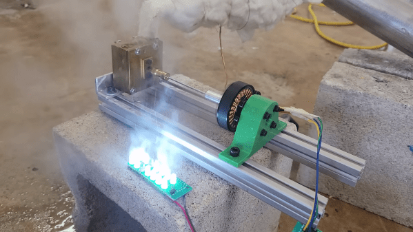
[Hyperspace Pirate] based the turbine design on 3D printed Pelton-style turbines he had previously experimented with, but milled it from brass using a CNC router. A couple of holes had to be drilled in the side of the rotor to balance it. The shaft drives a brushless DC motor to convert the energy from the expanding steam into electricity.

To avoid the long heat times required for a conventional boiler, [Hyperspace Pirate] decided to use a flash boiler. This involves heating up high-pressure water in a thin coil of copper tube, causing the water to boil as it flows down the tube. To produce the high-pressure water feed the propane tank for the burner was also hooked up to the water tank to pressurize it, removing the need for a separate pump or compressed air source. This setup allows the turbine to start producing power within twelve seconds of lighting the burner — significantly faster than a conventional boiler.

Throughout the entire video [Hyperspace Pirate] shows his calculation for the design and tests, making for a very informative demonstration. By hooking up a variable load and Arduino to the rectified output of the motor, he was able to measure the output power and efficiency. It came out to less than 1% efficiency for turning propane into electricity, not accounting for the heat loss of the boiler. The wide gaps between the turbine and housing, as well as the lack of a converging/diverging nozzle on the input of the turbine are likely big contributing factors to the low efficiency.

Like many of his other projects, the goal was the challenge of the project, not practicality or efficiency. From a gyro-stabilized monorail, to copper ingots from algaecide and and a DIY cryocooler, he has sure done some interesting ones.

Continue reading “Small Steam Generator Creates Educational Experience”

Clockwork Rover For Venus

Venus hasn’t received nearly the same attention from space programs as Mars, largely due to its exceedingly hostile environment. Most electronics wouldn’t survive the 462 °C heat, never mind the intense atmospheric pressure and sulfuric acid clouds. With this in mind, NASA has been experimenting with the concept of a completely mechanical rover. The [Beardy Penguin] and a team of fellow students from the University of Southampton decided to try their hand at the concept—video after the break.

The project was divided into four subsystems: obstacle detection, mechanical computer, locomotion (tracks), and the drivetrain. The obstacle detection system consists of three (left, center, right) triple-rollers in front of the rover, which trigger inputs on the mechanical computer when it encounters an obstacle over a certain size. The inputs indicate the position of each roller (up/down) and the combination of inputs determines the appropriate maneuver to clear the obstacle. [Beardy Penguin] used Simulink to design the logic circuit, consisting of AND, OR, and NOT gates. The resulting 5-layer mechanical computer quickly ran into the limits of tolerances and friction, and the team eventually had trouble getting their design to work with the available input forces.

Due to the high-pressure atmosphere, an on-board wind turbine has long been proposed as a viable power source for a Venus rover. It wasn’t part of this project, so it was replaced with a comparable 40 W electric motor. The output from a logic circuit goes through a timing mechanism and into a planetary gearbox system. It changes output rotation direction by driving the planet gear carrier with the sun gear or locking it in a stationary position.

As with many undergraduate engineering projects, the physical results were mixed, but the educational value was immense. They got individual subsystems working, but not the fully integrated prototype. Even so, they received several awards for their project and even came third in an international Simulink challenge. It also allowed another team to continue their work and refine the subsystems. Continue reading “Clockwork Rover For Venus”

Pushing The Plasma Limits With A Custom Flyback Transformer

For serious high-voltage plasma, you need a serious transformer. [Jay Bowles] from Plasma Channel is taking his projects to the next level, so he built a beefy 6000:1 flyback transformer.

[Jay] first built a driving circuit for his dream transformer, starting with a simple 555 circuit and three MOSFETs in parallel to handle 90 A of current. This led to an unexpected lesson on the necessity for transistor matching as one of them let out the Magic Smoke. On his second attempt, the 555 was swapped for an adjustable pulse generator module with a display, and a single 40 A MOSFET on the output.

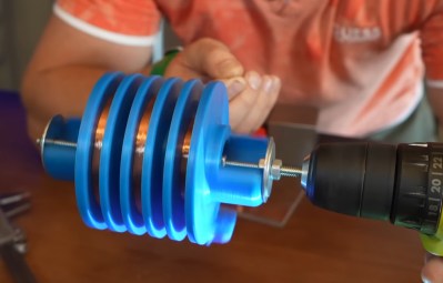
The transformer is built around a large 98×130 mm ferrite core, with eleven turns on the primary side. All the hard work is on the secondary side, where [Jay] designed a former to accommodate three winding sections in series. With the help of the [3D Printing Nerd], he printed PLA and resin versions but settled on the resin since it likely provided better isolation.

[Jay] spent six hours of quality time with a drill, winding 4000 feet (~1200 m) of enameled wire. On the initial test of the transformer, he got inch-long arcs on just 6 V and 15 W of input power. Before pushing the transformer to its full potential, he potted the secondary side in epoxy to reduce the chances of shorts between the windings.

Unfortunately, the vacuum chamber hadn’t removed enough of the air during potting, which caused a complete short of the middle winding as the input started pushing 11 V. This turned the transformer into a beautiful copper and epoxy paperweight, forcing [Jay] to start again from scratch.

On the following attempt [Jay] took his time during the potting process, and added sharp adjustable electrodes to act as voltage limiters on the output. The result is beautiful 2.25-inch plasma arcs on only 11 V and 100 W input power. This also meant he could power it with a single 580 mAh 3S LiPo for power.

[Jay] plans to use his new transformer to test materials he intends to use in future plasma ball, ion thruster, and rail gun projects. We’ll be keeping an eye out for those!

Continue reading “Pushing The Plasma Limits With A Custom Flyback Transformer”

Modular Magnetic LED Matrix

[bitluni] seems rather fond of soldering lots of LEDs, and fortunately for us the result is always interesting eye candy. The latest iteration of this venture features 8 mm WS2812D-F8 addressable LEDs, offering a significant simplification in electronics and the potential for much brighter displays.

The previous version used off-the-shelf 8×8 LED panels but had to be multiplexed, limiting brightness, and required a more complex driver circuit. To control the panel, [bitluni] used the ATtiny running the MegaTinyCore Arduino core. Off-the-shelf four-pin magnetic connectors allow the panels to snap together. They work well but are comically difficult to solder since they keep grabbing the soldering iron. [bitluni] also created a simple battery module and 3D printed neat enclosures for everything.

Having faced the arduous task of fixing individual LEDs on massive LED walls in the past, [bitluni] experimented with staggered holes that allow through-hole LEDs to be plugged in without soldering. Unfortunately, with long leads protruding from the back of the PCB, shorting became an immediate issue. While he ultimately resorted to soldering them for reliability, we’re intrigued by the potential of refining this pluggable design.

The final product snapped together satisfyingly, and [bitluni] programmed a simple animation scheme that automatically updates as panels are added or removed. What would you use these for? Let us know in the comments below. Continue reading “Modular Magnetic LED Matrix”

Levitating Magnet In A Spherical Copper Cage

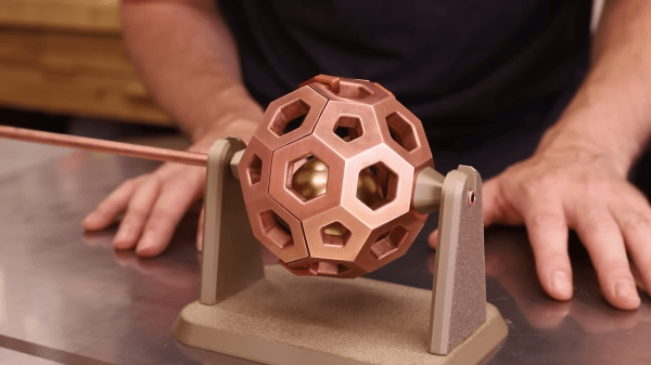
Lenz’s Law is one of those physics tricks that look like magic if you don’t understand what’s happening. [Seth Robinson] was inspired by the way eddy currents cause a cylindrical neodymium magnet to levitate inside a rotating copper tube, so he cast a spherical copper cage to levitate a magnetic sphere.

Metal casting is an art form that might seem simple at first, but is very easy to screw up. Fortunately [Seth] has significant experience in the field, especially lost-PLA metal casting. While the act of casting is quick, the vast majority of the work is in the preparation process. Video after the break.

[Seth] started by designing and 3D printing a truncated icosahedron (basically a low-poly sphere) in two interlocking halves and adding large sprues to each halve. Over a week, the PLA forms were repeatedly coated in layers of ceramic slurry and silica sand, creating a thick shell around them. The ceramic forms were then heated to melt and pour out the PLA and fired at 870°C/1600°F to achieve full hardness.

With the molds prepared, the molten copper is poured into them and allowed to cool. To avoid damaging the soft copper parts when breaking away the mold, [Seth] uses a sandblaster to cut it away sections. The quality of the cast parts is so good that 3D-printed layer lines are visible in the copper, but hours of cleanup and polishing are still required to turn them into shiny parts. Even without the physics trick, it’s a work of art. A 3d printed plug with a brass shaft was added on each side, allowing the assembly to spin on a 3D-printed stand.

[Seth] placed a 2″ N52 neodymium spherical magnet inside, and when spun at the right speed, the magnet levitated without touching the sides. Unfortunately, this effect doesn’t come across super clearly on video, but we have no doubt it would make for a fascinating display piece and conversation starter.

Using and abusing eddy currents makes for some very interesting projects, including hoverboards and magnetic torque transfer on a bicycle.

Continue reading “Levitating Magnet In A Spherical Copper Cage”

Solar Planes Are Hard

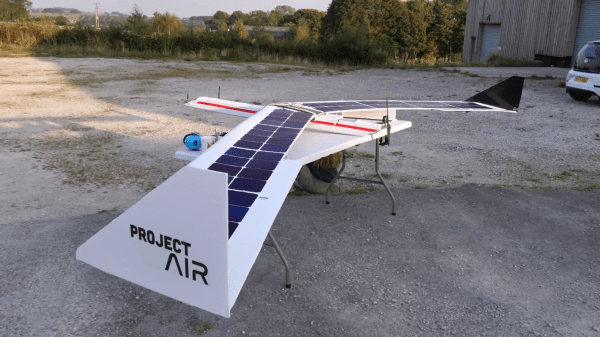
A regular comment we see on electric aircraft is to “just add solar panels to the wings.” [James] from Project Air has been working on just such a solar plane, and as he shows in the video after the break, it is not a trivial challenge.

A solar RC plane has several difficult engineering challenges masquerading as one. First, you need a solid, efficient airframe with enough surface area for solar panels. Then, you need a reliable, lightweight, and efficient solar charging system and, finally, a well-tuned autopilot to compensate for a human pilot’s limited endurance and attention span.

In part one of this project, a fault in the electrical system caused a catastrophe so James started by benching all the electricals. He discovered the MPPT controller had a battery cutoff feature that he was unaware of, which likely caused the crash. His solution was to connect the solar panels to the input of a 16.7 V voltage regulator—just under the fully charged voltage of a 4S LiPo battery— and wire the ESC, control electronics, and battery in parallel to the output. This should keep the battery charged as long as the motor doesn’t consume too much power.

After rebuilding the airframe and flight testing without the solar system, [James] found the foam wing spars were not up to the task, so he added aluminum L-sections for stiffness. The solar panels and charging system were next, followed by more bench tests. On the test flight, it turned out the aircraft was now underpowered and struggled to gain altitude thanks to the added weight of the solar system. With sluggish control responses,[James] eventually lost sight of it behind some trees, which led to a flat spin and unplanned landing.

Fortunately, the aircraft didn’t sustain any damage, but [James] plans to redesign it anyway to reduce the weight and make it work with the existing power system.

We’ve seen several solar planes from [rctestflight] and meticulously engineered versions from [Bearospace Industrues]. If long flight times is primarily what you are after, you can always ditch the panels and  use a big battery for 10+ hour flights.

Continue reading “Solar Planes Are Hard”