Heathkit Signal Generator Gets An Update

[DTSS_Smudge] correctly intuits that if you are interested in an old Heathkit signal generator, you probably already know how to solder. So, in a recent video, he focused on the components he decided to update for safety and other reasons. Meanwhile, we get treated to a nice teardown of this iconic piece of test gear.

If you didn’t grow up in the 1960s, it seems strange that the device has a polarized line cord with one end connected to the chassis. But that used to be quite common, just like kids didn’t wear helmets on bikes in those days.

A lot of TVs were “hot chassis” back then, too. We were always taught to touch the chassis with the back of your hand first. That way, if you get a shock, the associated muscle contraction will pull your hand away from the electricity. Touching it normally will make you grip the offending chassis hard, and you probably won’t be able to let go until someone kindly pulls the plug or a fuse blows.

These signal generators were very common back in the day. A lot of Heathkit gear was very serviceable and more affordable than the commercial alternatives. In 1970, these cost about $32 as a kit or $60 already built. While $32 doesn’t sound like much, it is equivalent to $260 today, so not an impulse buy.

Some of the parts are simply irreplaceable. The variable capacitor would be tough to source since it is a special type. The coils would also be tough to find replacements, although you might have luck rewinding them if it were necessary.

We are spoiled today with so many cheap quality instruments available. However, there was something satisfying about building your own gear and it certainly helped if you ever had to fix it.

There was so much Heathkit gear around that even though they’ve been gone for years, you still see quite a few units in use. Not all of their gear had tubes, but some of our favorite ones did.

A Modern PC With A Retro OS

Despite the rise of ARM processors in more and more computers from embedded systems to daily driver PCs, the x86 architecture maintains a stronghold in the computing space that won’t be going away anytime soon. One of the main drivers of this is its beachhead in industrial systems; the x86 architecture is backwards-compatible farther back than many of us have been alive and in situations where machines need to run for years with minimum downtime it’s good to know you can grab any x86 system off the shelf and it’ll largely work. This is also true for gaming, so if you’re like [Yeo Kheng Meng] and want to run games like DOOM natively on modern hardware it’s certainly possible, although there are a few catches.

This build goes into the design of a modern AMD Ryzen 5 desktop computer, with all of the components selected specifically for their use running software more than three decades old now. [Yeo Kheng Meng] is targeting DOS 6.22 as his operating system of choice, meaning that modern EFI motherboards won’t necessarily work. He’s turned to business class products as a solution for many of these issues, as motherboards targeting business and industrial customers often contain more support for antiquated hardware like PS/2 and parallel ports while still having modern amenities like DDR5 memory slots. PS/2 ports additionally are an indicator that the motherboard will supports older non-EFI boot modes (BIOS) and can potentially run DOS natively. Everything here can also run modern operating systems, since he isn’t building this system only to run DOS and retro games.

Beyond the motherboard choice, he’s also using a Soundblaster card for audio which is a design choice generally relegated to history, but still used in modern gaming by a dedicated group. There’s also a floppy drive running via a USB header adapter cable. Of course, there are a few problems running DOS and other era-appropriate software natively on such incomprehensibly fast hardware (by early 90s standards). Some video games were hard coded to the processor clock of the x86 process of the era, so increasing the clock speed orders of magnitude results in several playability issues. In emulators it’s easier to provide an artificially slow clock speed, but on real hardware this isn’t always possible. But [Yeo Kheng Meng] has done a lot to get this modern computer running older software like this. Another take we’ve seen for retro gaming on original hardware is this system which uses a brand-new 486 processor meant for use in industrial settings as well.

Give Your SMD Components A Lift

When you are troubleshooting, it is sometimes useful to disconnect a part of your circuit to see what happens. If your new PCB isn’t perfect, you might also need to add some extra wires or components — not that any of us will ever admit to doing that, of course. When ICs were in sockets, it was easy to do that. [MrSolderFix] shows his technique for lifting pins on SMD devices in the video below.

He doesn’t use anything exotic beyond a microscope. Just flux, a simple iron, and a scalpel blade. Oh, and very steady hands. The idea is to heat the joint, gently lift the pin with the blade, and wick away excess solder. If you do it right, you’ll be able to put the pin back down where it belongs later. He makes the sensible suggestion of covering the pad with a bit of tape if you want to be sure not to accidentally short it during testing. Or, you can bend the pin all the way back if you know you won’t want to restore it to its original position.

Continue reading “Give Your SMD Components A Lift”

A Wobble Disk Air Motor With One Moving Part

In general, the simpler a thing is, the better. That doesn’t appear to apply to engines, though, at least not how we’ve been building them. Pistons, cranks, valves, and seals, all operating in a synchronized mechanical ballet to extract useful work out of some fossilized plankton.

It doesn’t have to be that way, though, if the clever engineering behind this wobbling disk air engine is any indication. [Retsetman] built the engine as a proof-of-concept, and the design seems well suited to 3D printing. The driven element of the engine is a disk attached to the equator of a sphere — think of a model of Saturn — with a shaft running through its axis. The shaft is tilted from the vertical by 20° and attached to arms at the top and bottom, forming a Z shape. The whole assembly lives inside a block with intake and exhaust ports. In operation, compressed air enters the block and pushes down on the upper surface of the disk. This rotates the disc and shaft until the disc moves above the inlet port, at which point the compressed air pushes on the underside of the disc to continue rotation.

[Resetman] went through several iterations before getting everything to work. The main problems were getting proper seals between the disc and the block, and overcoming the friction of all-plastic construction. In addition to the FDM block he also had one printed from clear resin; as you can see in the video below, this gives a nice look at the engine’s innards in motion. We’d imagine a version made from aluminum or steel would work even better.

If [Resetman]’s style seems familiar, it’s with good reason. We’ve featured plenty of his clever mechanisms, like this pericyclic gearbox and his toothless magnetic gearboxes.

Continue reading “A Wobble Disk Air Motor With One Moving Part”

For Desalination, Follow The Sun

It’s easy to use electricity — solar-generated or otherwise — to desalinate water. However, traditional systems require a steady source of power. Since solar panels don’t always produce electricity, these methods require some way to store or acquire power when the solar cells are in the dark or shaded. But MIT engineers have a fresh idea for solar-powered desalination plants: modify the workload to account for the amount of solar energy available.

This isn’t just a theory. They’ve tested community-sized prototypes in New Mexico for six months. The systems are made especially for desalinating brackish groundwater, which is accessible to more people than seawater. The goal is to bring potable water to areas where water supplies are challenging without requiring external power or batteries.

The process used is known as “flexible batch electrodialysis” and differs from the more common reverse osmosis method. Reverse osmosis, however, requires a steady power source as it uses pressure to pump water through a membrane. Electrodialysis is amenable to power fluctuations, and a model-based controller determines the optimal settings for the amount of energy available.

There are other ways to use the sun to remove salt from water. MIT has dabbled in that process, too, at a variety of different scales.

The 2024 Hackaday Supercon SAO Badge Reveal

We’ve been hinting at it for a few months now, running a series of articles on SAOs, then a Supercon Add-On Challenge. We even let on that the badge would have space for multiple SAOs this year, but would you believe six?

Way back in 2017ish, Hackaday’s own [Brian Benchoff] and the [AND!XOR] crew thought it would be funny and useful to create a “standard” for adding small custom PCB art-badges onto bigger conference badges. The idea was to keep it quick and dirty, uncomplicated and hacky, and the “Shitty” Add On was born. The badge community took to this like wildfire. While the community has moved on from the fecal humor, whether you call these little badgelets “SAOs”, “Simple Add-Ons”, or even “Supercon-8 Add Ons”, there’s something here for everyone. So if you’ve already got some SAOs in a drawer, bring them to this year’s Supercon and show them off!

Continue reading “The 2024 Hackaday Supercon SAO Badge Reveal”

Pushing The Plasma Limits With A Custom Flyback Transformer

For serious high-voltage plasma, you need a serious transformer. [Jay Bowles] from Plasma Channel is taking his projects to the next level, so he built a beefy 6000:1 flyback transformer.

[Jay] first built a driving circuit for his dream transformer, starting with a simple 555 circuit and three MOSFETs in parallel to handle 90 A of current. This led to an unexpected lesson on the necessity for transistor matching as one of them let out the Magic Smoke. On his second attempt, the 555 was swapped for an adjustable pulse generator module with a display, and a single 40 A MOSFET on the output.

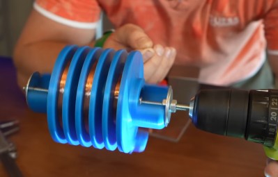
The transformer is built around a large 98×130 mm ferrite core, with eleven turns on the primary side. All the hard work is on the secondary side, where [Jay] designed a former to accommodate three winding sections in series. With the help of the [3D Printing Nerd], he printed PLA and resin versions but settled on the resin since it likely provided better isolation.

[Jay] spent six hours of quality time with a drill, winding 4000 feet (~1200 m) of enameled wire. On the initial test of the transformer, he got inch-long arcs on just 6 V and 15 W of input power. Before pushing the transformer to its full potential, he potted the secondary side in epoxy to reduce the chances of shorts between the windings.

Unfortunately, the vacuum chamber hadn’t removed enough of the air during potting, which caused a complete short of the middle winding as the input started pushing 11 V. This turned the transformer into a beautiful copper and epoxy paperweight, forcing [Jay] to start again from scratch.

On the following attempt [Jay] took his time during the potting process, and added sharp adjustable electrodes to act as voltage limiters on the output. The result is beautiful 2.25-inch plasma arcs on only 11 V and 100 W input power. This also meant he could power it with a single 580 mAh 3S LiPo for power.

[Jay] plans to use his new transformer to test materials he intends to use in future plasma ball, ion thruster, and rail gun projects. We’ll be keeping an eye out for those!

Continue reading “Pushing The Plasma Limits With A Custom Flyback Transformer”