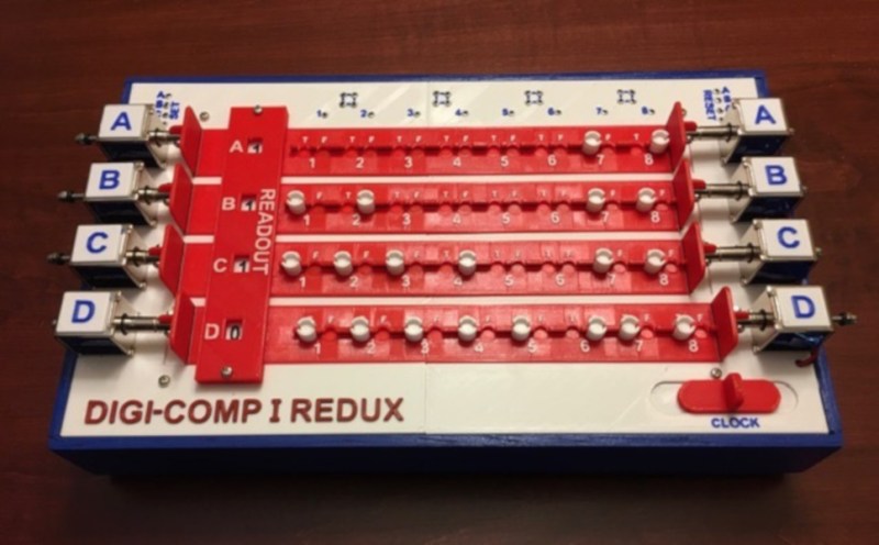
Most Hackaday readers are familiar with computers from the 70s and 80s, but what about ones even older than that? The Digi Comp 1 was a commercially available computer from the 1960s that actually cost less than a modern-day microcontroller. The catch? It was mechanical rather than electrical. Thanks to retro-wizard [Mike Gardi], now anyone can build a replica of one.
Admittedly the Digi Comp 1 was more of a toy than a tool, but it was still a working computer. It contained three flip-flops (memory) and had a lever that acted as a clock, allowing the user to perform boolean operations and some addition and subtraction. Certainly not advanced, but interesting nonetheless. [Mike]’s version of the Digi Comp 1 has an extra bit when compared to the original and includes some other upgrades, but largely remains faithful to the original design.
If you want to print one of these on your own, [Mike] has made all of the files available on Thingiverse. He has also experimented with other mechanical computers as well, including the sequel Digi Comp 2. We’ve seen some recent interest in that mechanical computer lately as well.


The original DigiComp didn’t have wires. It and Lectron were how I started on whatever this is.
Technically the original Digi-Comp I did have wires. The “clock rods” and the “logic rods” were made from stiff piano wire. Here is a link to the Thingiverse project for building one with a picture. Digi-Comp I was a small part of why I ended up in software development.
Rod logic? Sounds like an ancestor of technology in “Diamond Age”. ;)
Sure you’re not talking about “The Difference Engine”?
I don’t think it’s fair to call the Digicomp I’s clock and logic rods as “wires.” The material they’re made from is irrelevant; they’re part of the mechanism, and vital parts at that.
By that standard bicycle spokes are “stiff piano wire”.
Thanks for posting Bryan! While my version is more of an electro mechanical variant of the Digi-Comp I, there is a link in the Instructable to a Model of the original mechanical version done by Mark Ziemer that you can print and make.
Convince me it’s more of a computer than… https://www.1900s.org.uk/financial-calculators.htm
Some of those “computer” toys always seemed like a gussied up abacus/tally system where all operations were actually manual.
Digi-Comp I was truly programmable. It could be made to count, play Nim, perform Boolean algebra, and other simple tasks just by changing some programming pegs. Disappointingly it’s successor the Digi-Comp II, while interesting, was not. The DGII was more of a calculator (but with marbles :-). While what you say is true of some of these vintage machines, they always shipped with instructive and interesting manuals that were often the most valuable part of the offering.
As a kid who learned pounds, shillings and pence in Australia in the early 60s, that’s cool!
I left Australia just a few months before they went decimal in 1965
>Convince me it’s more of a computer than…
That’s easy. DigiComp I is programmable. The device you showed is an adding machine.
Although a very impressive build, it would be 100x cooler if there wasn’t an arduino hiding in the box.
That said, it does strike me as hilarious that the cheapest way to simulate a primitive computer is to take a computer with a billion times more processing power and hide it inside.
The irony is not lost on me. The original design was Arduinoless but proved unfeasible. Probably could have accomplished the same thing with discreet components but like most of us I had an Arduino lying around. Also had a Raspberry Pi available but that would have been even more ironic.
So what does the Arduino do? Switch relays in a sequence.
If so, you could have gone the old-fashioned way and made a ratcheting wheel.
The Arduino has to detect that the CLOCK has been cycled, read the current state of the system, then engage the appropriate solenoids to move the flip-flops based on that state. Rinse and repeat. I think that this could be accomplished with an 8-bit latch and a couple of 555s to debounce the CLOCK switch and engage the solenoids for an appropriate amount of time (about 200ms). Buts as I said I had an Arduino gathering dust.
With respect, I think you guys are missing the point. The whole purpose of the Digi-Comps was to make the workings of real computers accessible to kids and grownups who have no idea how computers work.
Kids today can easily find exotic electronic gadgets that will respond to their inputs — their smart phones, for sure — but electrons flowing inside a black box doesn’t tell them ANYTHING about how the gates work. Digi-Comp’s stated goal was to show people what’s really going on using mechanisms that they can _SEE_ working, at a rate that’s slow enough to see the flip-flops actually change state.
Like RW’s adding machine, Digi-Comp II was a “mere” adding machine, but again it was all mechanical, so its users could watch the balls roll and flip-flops flip at a speed slow enough to watch things happen.
While the Digi-Comp II really was a single-purpose “adding machine,” it did have an accumulator and two input registers, and it could also add,subtract (with a really neat negation algorithm), multiply and device, according to commands set up by the user. So AFAIC it’s a sho-nuff computer.
Could have use a Parallax BASIC Stamp. :)
Megardi said “The original design was Arduinoless but proved unfeasible. ”
How so? Because it was too slow? That was the whole point: To show how flip-flops work, and let the student watch them change states in accordance with the “program” set by the user.
Not enough gates? That’s true, but adding even one more flip-flop requires many more sense and action mechanisms.
Didn’t use electronics? Again, that’s the whole point. It’s very difficult to watch electrons flowing through a wire. The DIgi-Comps let the students SEE what’s going on.
I bought my daughter (age 10) both Digi-Comp I and II, and she loved them both. Still does, these 50 years later. Fact is, I learned a lot from them too.
She was in an advanced math class (4th grade). She took Digi-Comp II to class, and demonstrated it. The teacher called me to come and teach more. She was struggling with teaching them binary arithmetic, and frantic for some help.
We took Digi-Comp II, and I gave a lecture on it. In one hour, we covered not only the binary number base, but also octal and hex. Those (scary bright) kids got it all, instantly.
If you want to know how computers REALLY work on a little more electronic level, look at Ben Eater’s excellent YouTube video series on building an 8-bit computer, starting here: https://www.youtube.com/watch?v=HyznrdDSSGM. He starts off at the simplest possible level (gates and clocks) and goes on to explain every minute thing that goes on inside a simple computer, as he builds one from TTL chips. His explanations of circuit operation are the best I’ve ever seen. Plenty of LEDs to show you the state of everything as you step through your programs. Since then he has done shorter series that go into detail on how communications protocols work, how to build a (real) computer starting with a 6502 CPU and other more sophisticated topics.
It was the work that people like Jim did and the 8-Bit Guy (David Murray’s) Dream Computer series (https://youtu.be/sg-6Cjzzg8s) that inspired me to try my hand at making a new vintage computer.
So you must really like my Digi-Comp II replica since it’s almost a perfect reproduction:
https://www.instructables.com/id/Digi-Comp-II-Replica/
While your at it check out my Minivac 601 and Geniac projects.
Thanks Megardi, I already printed Dr. Nim and Think-A-Dot, and I’ll definitely try this one too. Although I like your recreation of the Digi-comp II more, as it is completely mechanical.
Cool. If you are looking for completely mechanical might I suggest Mark Ziemer’s Digi-Comp I replica. You can find it here:
https://www.thingiverse.com/thing:1477209
Mike
Or you can try out my Turbo Entabulator project – It even uses 3D-printed punch cards to store the program!
https://www.thingiverse.com/thing:101105
Looks nice in powder blue, a very 1950’s – 1960’s color. Does it have linear spurving bearings? https://www.youtube.com/watch?v=Ac7G7xOG2Ag
Wow. Added to my thins to make list for sure.
WOW. Added to my things to make list!
This is completely wrong. The whole point of the DigiComp I was that it was a digital logic machine that was completely exposed – you could tell exactly what it was doing, and how, just by looking at it. It was more like a registered PLD than a computer, but the whole point is lost by having the works hidden away in an Arduino.
In this implementation the Arduino merely replaces the complicated set of cutouts on the two clock sliders that engaged the appropriate clock rods to move the flip flops when you manually cycled the clock. They were truly a marvel of engineering so I agree that something is lost here for sure. On the other hand this new implementation completely exposes the “programming model”. The user can understand just by looking at the “programming peg” positions and the solenoid wiring (clock pegs equivalent) what the next state of the machine will be. They can “program” all of the experiments in the instruction manual and see the results when the operate the CLOCK. They don’t have to see the underlying implementation to get most of the value from the machine IMHO.
I realize that the horse is long dead, yet I will continue the beating. Seeing that moving a peg causes a different motor to turn doesn’t demystify ANYTHING, while seeing what effect those pegs have on the moving parts of a mechanism (e.g., on the original DC I) DOES. You might as well be watching an animation of the DigiComp I on a smartphone.