Clockwork Rover For Venus

Venus hasn’t received nearly the same attention from space programs as Mars, largely due to its exceedingly hostile environment. Most electronics wouldn’t survive the 462 °C heat, never mind the intense atmospheric pressure and sulfuric acid clouds. With this in mind, NASA has been experimenting with the concept of a completely mechanical rover. The [Beardy Penguin] and a team of fellow students from the University of Southampton decided to try their hand at the concept—video after the break.

The project was divided into four subsystems: obstacle detection, mechanical computer, locomotion (tracks), and the drivetrain. The obstacle detection system consists of three (left, center, right) triple-rollers in front of the rover, which trigger inputs on the mechanical computer when it encounters an obstacle over a certain size. The inputs indicate the position of each roller (up/down) and the combination of inputs determines the appropriate maneuver to clear the obstacle. [Beardy Penguin] used Simulink to design the logic circuit, consisting of AND, OR, and NOT gates. The resulting 5-layer mechanical computer quickly ran into the limits of tolerances and friction, and the team eventually had trouble getting their design to work with the available input forces.

Due to the high-pressure atmosphere, an on-board wind turbine has long been proposed as a viable power source for a Venus rover. It wasn’t part of this project, so it was replaced with a comparable 40 W electric motor. The output from a logic circuit goes through a timing mechanism and into a planetary gearbox system. It changes output rotation direction by driving the planet gear carrier with the sun gear or locking it in a stationary position.

As with many undergraduate engineering projects, the physical results were mixed, but the educational value was immense. They got individual subsystems working, but not the fully integrated prototype. Even so, they received several awards for their project and even came third in an international Simulink challenge. It also allowed another team to continue their work and refine the subsystems. Continue reading “Clockwork Rover For Venus”

A robot mop on a wooden floor

A Turbocharged Robot Mop To Save Your Date

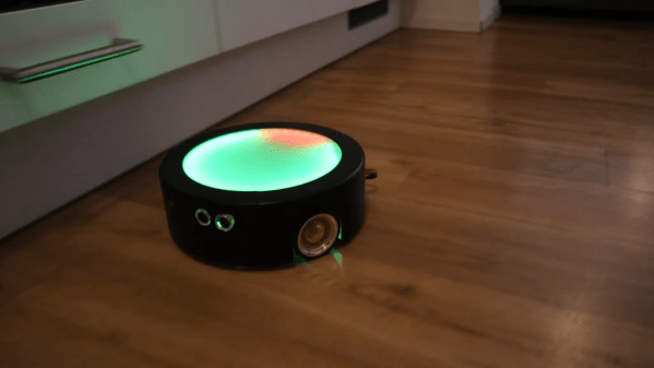
Cleaning robots are great and all, but they don’t really excel when it comes to speed. If your room looks like a pigsty and your Tinder date is arriving in twenty minutes, you’ll need more than a Roomba to make a good impression. [Luis Marx] ran into this exact problem and decided to solve it by building the world’s fastest cleaning robot (video, embedded below).

[Luis] built his ‘bot from the ground up, inspired by the design of your average robot vacuum: round, with two driven wheels and some sensors to avoid obstacles. A sturdy aluminium plate forms the chassis, onto which two powerful motors are placed to drive a pair of large-diameter wheels. The robot’s body is made from 3D-printed components and sports a huge LED display on top that functions as a speedometer of sorts.

Building a vacuum system turned out to be rather difficult, and since [Luis] already had a robot vacuum anyway, he decided to make this a robot mop instead. A little tank stores water and soap, which is pumped onto a microfibre cloth that’s attached using a magnetic strip. Obstacle avoidance is implemented through three ultrasonic distance sensors: when the robot is about to run into something it will brake and turn in the direction where it senses the most empty space.

All of that sounds great, but what about the speed? According to [Luis]’s calculations, it should be able to reach 60 km/h, although his living room is too small to put that into practice. Whether it will provide much in the way of cleaning at that speed is debatable too, but who cares: having your own ultra-high-speed robot mop will definitely impress your date more than any amount of cleaning.

We’ve featured a home-made robot mop before, but it looks excruciatingly slow compared to this one. If you’re planning to build zippy indoor robots, you might want to look into fast navigation systems like tracking ceiling lights.

Continue reading “A Turbocharged Robot Mop To Save Your Date”

LEONARDO, a hybrid drone and bipedal robot

LEONARDO: The Hopping, Flying Bipedal Robot

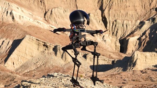
We appear to have a new entry atop the “Robots That Creep Us Out” leader board: meet LEONARDO, the combination quadcopter/bipedal robot.

LEONARDO, a somewhat tortured name derived from “LEgs ONboARD drOne,” is actually just what it appears to be: a quadcopter with a set of legs. It comes to us from Caltech’s Center for Autonomous Systems and Technologies, and the video below makes it easy to see what kind of advantages a kinematic mash-up like this would offer. LEO combines walking and flying to achieve a kind of locomotion that looks completely alien, kind of a bouncy, tip-toeing step that really looks like someone just learning how to walk in high heels. The upper drone aspect of LEO provides a lot of the stabilization needed for walking; the thrust from the rotors is where that bouncy compliance comes from. But the rotors can also instantly ramp up the thrust so LEO can fly over obstacles, like stairs. It’s also pretty good at slacklining and skateboarding, too.

It’s easy to see how LEO’s multimodal locomotion system solves — or more accurately, avoids — a number of the problems real-world bipedal robots are going to experience. For now, LEO is pretty small — only about 30″ (76 cm) tall. And it’s rather lightly constructed, as one would expect for something that needs to fly occasionally. But it’s easy to see how something like this could be scaled up, at least to a point. And LEO’s stabilization system might be just what its drunk-walking cousin needs.

Continue reading “LEONARDO: The Hopping, Flying Bipedal Robot”

A Mechanical Edge-Avoiding Robot

In the age of cheap sensors and microcontrollers, it’s easy to forget that there might be very simple mechanical solutions to a problem. [gzumwalt]’s 3D printed mechanical edge avoiding robot is a beautifully  elegant example of this.

The only electric components on this robot is a small geared DC motor and a LiPo battery. The motor drives a shaft fixed to a wheel on one side, while the opposite wheel is free-spinning. A third wheel is mounted perpendicular to the other two in the center of the robot, and is driven from the shaft by a bevel gear. The third wheel is lifted off the surface by a pair of conical wheels on a pivoting axle. When one of these conical wheels go over the edge of whatever surface it’s driving on, it lowers front and brings the third wheel into contact with the surface, spinning the robot around until both front wheels are back on the surface.

Mechanical alternatives for electronic systems are easily overlooked, but are often more reliable and rugged in hostile environments. NASA is looking at sending a rover to Venus, but with surface temperatures in excess of 450 °C and atmospheric pressure 92 times that of Earth, conventional electronics won’t survive. Earlier in the year NASA ran a design competition for a completely mechanical obstacle detection system for use on Venus.

[gzumwalt] is a very prolific designer on ingenious 3D printed mechanical devices. This mechanism could also be integrated in his walking fridge rover to explore the front of your fridge without falling off. Continue reading “A Mechanical Edge-Avoiding Robot”

Obstacle Avoidance For Drones, Learned From Mosquitoes

Our understanding of the sensory capabilities of animals has a lot of blanks, and often new discoveries serve as inspiration for new technology. Researchers from the University of Leeds and the Royal Veterinary College have found that mosquitos can navigate in complete darkness by detecting the subtle changes in the air flow created when they fly close to obstacles. They then used this knowledge to build a simple but effective sensor for use on drones.

Extremely sensitive receptors at the base of the antennae on mosquitoes’ heads, called the Johnston’s organ, allow them to sense these tiny changes in airflow. Using fluid dynamics simulations based on high speed photography, the researchers found that the largest changes in airflow occur over the mosquito’s head, which means the receptors are in exactly the right place. From their data, scientists predict that mosquitos could possibly detect surfaces at a distance of more than 20 wing lengths. Considering how far 20 arm lengths is for us, that’s pretty impressive. If you can get past the paywall, you can read the full article from the Science journal.

Using their newfound knowledge, the researchers equipped a small drone with probe tubes connected to differential pressure sensors. Using these sensors the drone was able to effectively detect when it got close to the wall or floor, and avoid a collision. The sensors also require very little computational power because it’s only a basic threshold value. Check out the video after the break.

Although this sensing method might not replace ultrasonic or time-of-flight sensors for drones, it does show that there is still a lot we can learn from nature, and that simpler is usually better. We’ve already seen simple insect-inspired navigation for drone swarms, as well as an optical navigation device for humans that works without satellites and only requires a view of the sky. Thanks for the tip [Qes]! Continue reading “Obstacle Avoidance For Drones, Learned From Mosquitoes”

Low-cost Autonomous Rover Will Drive Your Projects

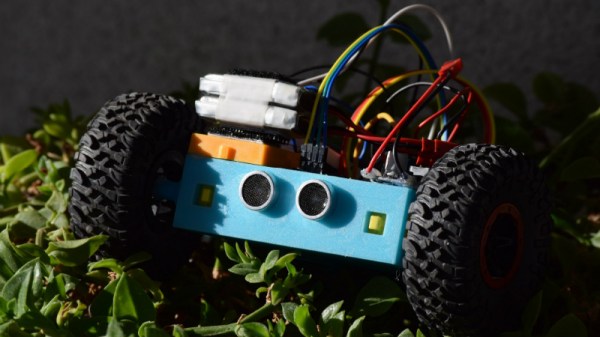
[Miguel] wanted to get more hands-on experience with Python, so he created a small robotic platform as a testbed. But as such things sometimes go, it turns out the robot he created is a worthy enough project in its own right. With a low total cost and highly flexible design, it might be exactly what you’re looking for. Who knows, it might even bootstrap that rover project that’s been wandering around the back of your mind.

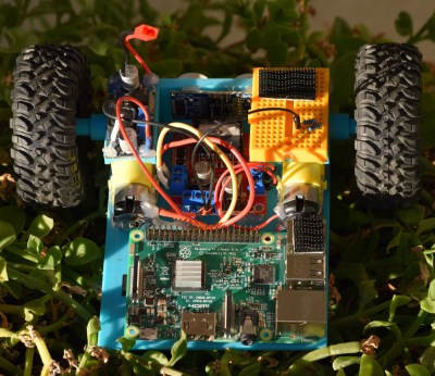
The robot makes use of an exceptionally simple 3D printed frame. No complicated suspension to worry about, no fasteners to hold together multiple printed parts. It’s just a single printed “L” shaped piece that has mounts for the motors and front sensor board. As designed it simply drags its tail around, which should work fine on smooth surfaces, but might need a bit of tweaking if you plan on taking your new robotic friend on an outdoor adventure.

There’s a big open area on the “tail” to mount a Raspberry Pi, but you could really put whatever board or microcontroller you wish here. In the nose is an HC-SR04 ultrasonic sensor, which [Miguel] is using to perform obstacle avoidance in his Python code. A dual H-Bridge motor driver controls the pair of gear motors in the front to provide propulsion and steering, and a buck converter steps down the 7.4V from the 2S LiPo battery to power the electronics. He’s even included a mini breadboard so you can add circuits or sensors as experimental payloads.

If you’re looking for a slightly more advanced 3D printed robotics platform, we’ve seen our fair share. From the nearly fully printed Watney to a tank that looks like it’s ready for front-line combat.

Hackaday Prize Entry: Visioneer Sensor HUD

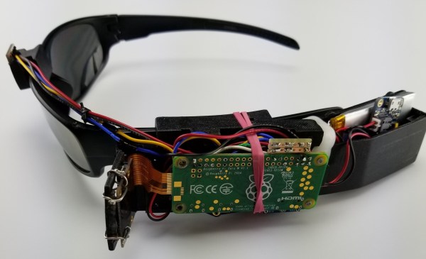
Only about two percent of the blind or visually impaired work with guide animals and assistive canes have their own limitations. There are wearable devices out there that take sensor data and turn the world into something a visually impaired person can understand, but these are expensive. The Visioneer is a wearable device that was intended as a sensor package for the benefit of visually impaired persons. The key feature: it’s really inexpensive.

The Visioneer consists of a pair of sunglasses, two cameras, sensors, a Pi Zero, and bone conduction transducers for audio and vibration feedback. The Pi listens to a 3-axis accelerometer and gyroscope, a laser proximity sensor for obstacle detection within 6.5ft, and a pair of NOIR cameras. This data is processed by neural nets and OpenCV, giving the wearer motion detection and object recognition. A 2200mA battery powers it all.

When the accelerometer determines that the person is walking, the software switches into obstacle avoidance mode. However, if the wearer is standing still, the Visioneer assumes you’re looking to interact with nearby objects, leveraging object recognition software and haptic/audio cues to relay the information. It’s a great device, and unlike most commercial versions of ‘glasses-based object detection’ devices, the BOM cost on this project is only about $100. Even if you double or triple that (as you should), that’s still almost an order of magnitude of cost reduction.