Making PCB Strip Filter Design Easy To Understand

We’ve always been fascinated by things that perform complex electronic functions merely by virtue of their shapes. Waveguides come to mind, but so do active elements like filters made from nothing but PCB traces, which is the subject of this interesting video by [FesZ].

Of course, it’s not quite that simple. A PCB is more than just copper, of course, and the properties of the substrate have to be taken into account when designing these elements. To demonstrate this, [FesZ] used an online tool to design a bandpass filter for ADSB signals. He designed two filters, one using standard FR4 substrate and the other using the more exotic PTFE.

He put both filters to the test, first on the spectrum analyzer. The center frequencies were a bit off, but he took care of that by shortening the traces slightly with a knife. The thing that really stood out to us was the difference in insertion loss between the two substrates, with the PTFE being much less lossy. The PTFE filter was also much more selective, with a tighter pass band than the FR4. PTFE was also much more thermostable than FR4, which had a larger shift in center frequency and increased loss after heating than the PTFE. [FesZ] also did a more real-world test and found that both filters did a good job damping down RF signals across the spectrum, even the tricky and pervasive FM broadcast signals that bedevil ADSB experimenters.

Although we would have liked a better explanation of design details such as via stitching and trace finish selection, we always enjoy these lessons by [FesZ]. He has a knack for explaining abstract concepts through concrete examples; anyone who can make coax stubs and cavity filters understandable has our seal of approval.

Continue reading “Making PCB Strip Filter Design Easy To Understand”

Electric Candle Replaces Flame With Plasma

Ah, the charm of candlelight! Nothing says “romance” — or “extended power outage” — like the warm, soft glow of a real candle. But if you’re not a fan of burning wax for whatever reason, this electric plasma candle may be just the thing to build for your next dinner for two.

This re-imagining of the humble candle comes to us by way of plasma super-fan [Jay Bowles], who has a lot of experience with plasmas and the high-voltage circuits that often go along with them. Even so, he had to enlist help with the circuit, with is essentially a 10-MHz Class-E oscillator, from [Leon] at the Teslaundmehr channel on YouTube. The most prominent feature of the build is the big resonator coil, surrounded by the shorter primary coil and sitting atop the heatsink for the MOSFET driver. [Jay]’s usual acrylic-rich style is well represented here, and the resulting build is quite lovely.

The tuning process, though, sounds like it was pure torture. It took a lot of tweaking — and a lot of MOSFETs — to get the candle to produce a stable flame. But once it did, the results were striking. The plasma coming off the breakout point on the resonator coil is pretty much the same size, shape, and — occasionally — the color as a candle flame. It’s also hot enough to do some damage, so do be careful if you build this. We’ve included both [Jay]’s and [Leon]’s videos below; [Leon]’s has great step-by-step build instructions.

We’ve been following [Jay]’s journey through the plasmaverse for a while now, from his cheap and simple Tesla coils to using corona discharge to clean his hands. He even hosted a Hack Chat on the subject last year.

Note: [Jay] reached out to us after publication about mitigating RF noise. He does his experiments inside a steel-reinforced concrete building with grounded metal screens over the windows. An RF-wizard friend has checked across the spectrum and detected no leaks to the outside. Sounds like the business to us.

Continue reading “Electric Candle Replaces Flame With Plasma”

Tiny Transmitter Brings Out The Spy Inside You

When it comes to surveillance, why let the government have all the fun? This tiny spy transmitter is just the thing you need to jumpstart your recreational espionage efforts.

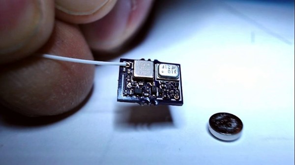
We kid, of course — you’ll want to stay within the law of the land if you choose to build [TomTechTod]’s diminutive transmitter. Barely bigger than the 337 button cell that powers it, the scrap of PCB packs a fair number of surface mount components, most in 0201 packages. Even so, the transmitter is a simple design, with a two transistor audio stage amplifying the signal from the MEMS microphone and feeding an oscillator that uses a surface acoustic wave (SAW) resonator for stability. The bug is tuned for the 433-MHz low-power devices band, and from the video below, it appears to have decent range with the random wire antenna — maybe 50 meters. [TomTechTod] has all the build files posted, including Gerbers and a BOM with Digikey part numbers, so it should be easy to make one for your fieldcraft kit.

If you want to dive deeper into the world of electronic espionage, boy, have we got you covered. Here’s a primer on microphone bugs, a history of spy radios, or how backscatter was used to bug an embassy.

Continue reading “Tiny Transmitter Brings Out The Spy Inside You”

Doppler Module Teardown Reveals The Weird World Of Microwave Electronics

Oscillators with components that aren’t electrically connected to anything? PCB traces that function as passive components based solely on their shape? Slots and holes in the board with specific functions? Welcome to the weird and wonderful world of microwave electronics, brought to you through this teardown and analysis of a Doppler microwave transceiver module.

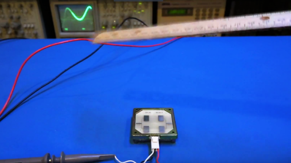
We’ve always been fascinated by the way conventional electronic rules break down as frequency increases. The Doppler module that [Kerry Wong] chose to pop open, a Microsemi X-band transceiver that goes for about $10 on eBay right now, has vanishingly few components inside. One transistor for the local oscillator, one for the mixer, and about three other passives are the whole BOM. That the LO is tuned by a barium titanate slug that acts as a dielectric resonator is just fascinating, as is the fact that PB traces can form a complete filter network just by virtue of their size and shape. Antennas that are coupled to the transceiver through an air gap via slots in the board are a neat trick too.

[Kerry] analyzes all this in the video below and shows how the module can be used as a sensor. If you need a little more detail on putting these modules to work, we’ve got some basic circuits you can check out.

Continue reading “Doppler Module Teardown Reveals The Weird World Of Microwave Electronics”

Trio Of Magnetrons Power A Microwave Rifle

Can you build a working EM weapon from three microwave ovens? Apparently, yes. Should you do so? Maybe not when the best safety gear you can muster is a metallized Mylar film fetish suit and a Hershey’s Kiss hat.

Proving that language need not be a barrier to perfect understanding of bad ideas, the video below tells you all you need to know, even without subtitles in the non-Russian language of your choice. [KREOSAN]’s build is obnoxiously obvious — three magnetrons mounted on a tin can “resonator” with a foil-covered waveguide at the business end. The magnetrons are tickled by a stun-gun that’s powered by a pack of 18650 batteries. The video shows some “experiments”, like lighting up unpowered CFL bulbs from about 15 meters away and releasing the Blue Smoke from the electrical system of a running motor scooter. Assuming they weren’t added in post, the artifacts in the video belie the gun’s lack of shielding for the operator. We doubt any of the ad hoc safety gear would provide any protection from the resulting microwaves, but we also doubt that it matters much when things have gotten this far.

We’re not too sure about this one — some of the zapping stunts look a little too conveniently explosive. It’s hard to tell the details without a translation, so maybe one of our Russian-speaking readers can pitch in on the comments. Although this isn’t [KRESOAN]’s first microwave rodeo, having melted a few lightbulbs with magnetrons before. Even seeing this we still consider EMP Weapons a figment of Hollywood’s imagination.

Continue reading “Trio Of Magnetrons Power A Microwave Rifle”

Strobe Light Slows Down Time

Until the 1960s, watches and clocks of all kinds kept track of time with mechanical devices. Springs, pendulums, gears, oils, and a whole host of other components had to work together to keep accurate time. The invention of the crystal oscillator changed all of that, making watches and clocks not only cheaper, but (in general) far more accurate. It’s not quite as easy to see them in action, however, unless you’re [noq2] and you have a set of strobe lights.

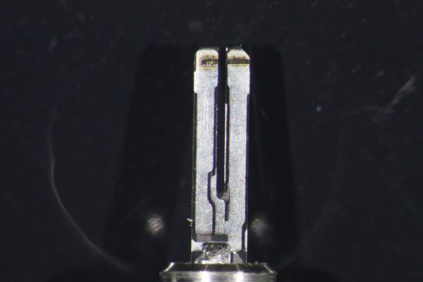
[noq2] used a Rigol DG4062 function generator and a Cree power LED as a high-frequency strobe light to “slow down” the crystal oscillators from two watches. The first one he filmed was an Accutron “tuning fork” movement and the second one is a generic 32,768 Hz quartz resonator which is used in a large amount of watches. After removing the casings and powering the resonators up, [noq2] tuned in his strobe light setup to be able to film the vibrations of the oscillators.

It’s pretty interesting to see this in action. Usually a timekeeping element like this, whether in a watch or a RTC, is a “black box” of sorts that is easily taken for granted. Especially since these devices revolutionized the watchmaking industry (and a few other industries as well), it’s well worthwhile to take a look inside and see how they work. They’re used in more than just watches, too. Want to go down the rabbit hole on this topic? Check out the History of Oscillators. Continue reading “Strobe Light Slows Down Time”

ESP8266 ESP07 Module DoA Fix

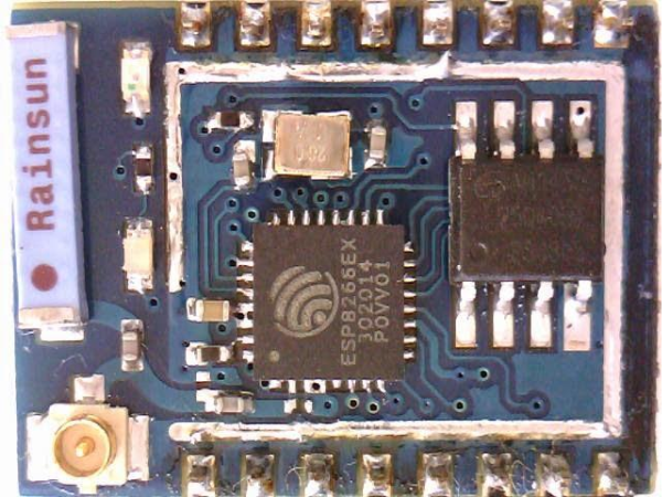
It seems the Far-East factories can’t churn out ESP8266 based modules fast enough to feed all the world’s hackers. Well, Pick-n-Place machines are human too, so it’s not too long before you end up with a messed up batch from a factory. [Tracker Johnny] found a bunch of ESP07 modules which had their resonator mounted the wrong way around, effectively making them DoA. The resonator mounting isn’t consistently wrong too – most have reported them 90 deg offset, while others had them 180 deg. off.

Unfortunately, you need some tools and skills to fix the error. The ESP07 modules have a metal shield which needs to be removed to access the resonator. This is best done using a hot air gun. With the cover removed, you need to de-solder the resonator, and put it back in the right orientation as shown in the pictures on [Tracker Johnny]’s blog. You can find other people reporting the same fault at this forum thread. Coming in the wake of the problem with magic smoke from ESP8266 based ESP01 modules we reported earlier, it seems obvious that quality comes at a cost.