Making PCB Strip Filter Design Easy To Understand

We’ve always been fascinated by things that perform complex electronic functions merely by virtue of their shapes. Waveguides come to mind, but so do active elements like filters made from nothing but PCB traces, which is the subject of this interesting video by [FesZ].

Of course, it’s not quite that simple. A PCB is more than just copper, of course, and the properties of the substrate have to be taken into account when designing these elements. To demonstrate this, [FesZ] used an online tool to design a bandpass filter for ADSB signals. He designed two filters, one using standard FR4 substrate and the other using the more exotic PTFE.

He put both filters to the test, first on the spectrum analyzer. The center frequencies were a bit off, but he took care of that by shortening the traces slightly with a knife. The thing that really stood out to us was the difference in insertion loss between the two substrates, with the PTFE being much less lossy. The PTFE filter was also much more selective, with a tighter pass band than the FR4. PTFE was also much more thermostable than FR4, which had a larger shift in center frequency and increased loss after heating than the PTFE. [FesZ] also did a more real-world test and found that both filters did a good job damping down RF signals across the spectrum, even the tricky and pervasive FM broadcast signals that bedevil ADSB experimenters.

Although we would have liked a better explanation of design details such as via stitching and trace finish selection, we always enjoy these lessons by [FesZ]. He has a knack for explaining abstract concepts through concrete examples; anyone who can make coax stubs and cavity filters understandable has our seal of approval.

Continue reading “Making PCB Strip Filter Design Easy To Understand”

Simple Chemistry To Metallize And Etch Silicon Chips

We’ve been eagerly following [ProjectsInFlight]’s stepwise journey toward DIY semiconductors, including all the ups and downs, false leads, and tedious optimizations needed to make it possible for the average hacker to make chips with readily available tools and materials.

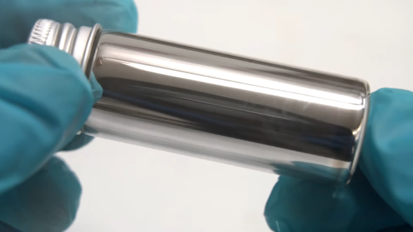
Next up is metallization, and spoiler alert: it wasn’t easy. In a real fab, metal layers are added to chips using some form of deposition or sputtering method, each of which needs some expensive vacuum equipment. [ProjectsInFlight] wanted a more approachable way to lay down thin films of metal, so he turned to an old friend: the silver mirror reaction. You may have seen this demonstrated in high school chemistry; a preparation of Tollen’s reagent, a mix of sodium hydroxide, ammonia, and silver nitrate, is mixed with glucose in a glass vessel. The glucose reduces the reagent, leaving the metallic silver to precipitate on the inside of the glass, which creates a beautiful silvered effect.

Despite some issues, the silvering method worked well enough on chips to proceed on, albeit carefully, since the layer is easily scratched off. [ProjectsInFlight]’s next step was to find an etchant for silver, a tall order for a noble metal. He explored piranha solutions, which are acids spiked with peroxide, and eventually settled on plain old white vinegar with a dash of 12% peroxide. Despite that success, the silver layer was having trouble sticking to the chip, much preferring to stay with the photoresist when the protective film was removed.

The solution was to replace the photoresist’s protective film with Teflon thread-sealing tape. That allowed the whole process from plating to etching to work, resulting in conductive traces with pretty fine resolution. Sure they’re a bit delicate, but that’s something to address another day. He’s come a long way from his DIY tube furnace used to put down oxide layers, and suffering through the search for oxide etchants and exploring photolithography methods. It’s been a fun ride so far, and we’re eager to see what’s next.

Continue reading “Simple Chemistry To Metallize And Etch Silicon Chips”

Wire race bearing

Adding Wire Races Improves 3D-Printed Bearings

Like a lot of power transmission components, bearings have become far easier to source than they once were. It used to be hard to find exactly what you need, but now quality bearings are just a few clicks away. They’re not always cheap though, especially when you get to the larger sizes, so knowing how to print your own bearings can be a handy skill.

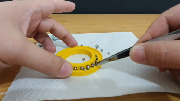
Of course, 3D-printed bearings aren’t going to work in every application, but [Eros Nicolau] has a plan for that. Rather than risk damage from frictional heating by running plastic or metal balls in a plastic race, he uses wire rings as wear surfaces. The first video below shows an early version of the bearing, where a pair of steel wire rings lines the 3D-printed inner and outer races. These worked OK, but suffered from occasional sticky spots and were a bit on the noisy side.

The second video shows version two, which uses the same wire-ring race arrangement but adds a printed ball cage to restrain the balls. This keeps things quieter and eliminates binding, making the bearing run smoother. [Eros] also added a bit of lube to the bearing, in the form of liquid PTFE, better known as Teflon. It certainly seemed to smooth things out. We’d imagine PTFE would be more compatible with most printed plastics than, say, petroleum-based greases, but we’d be keen to see how the bearings hold up in the long term.

Maybe you recall seeing big 3D-printed bearings around here before? You’d be right. And we’ve got you covered if you need to learn more about how bearings work — or lubricants, for that matter.

Continue reading “Adding Wire Races Improves 3D-Printed Bearings”

DIY Heavy Duty Linear Slides

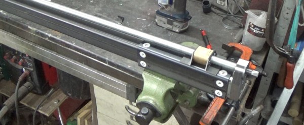
The rise of cost-effective CNC platforms like 3D printers, routers, and laser cutters has gone hand in hand with the availability of affordable and accurate linear rails and extrusions. However, they quickly become expensive when you need something for heavy loads. [Andy Pugh] found himself in need of a large linear slide, so he resorted to making his own with steel square tubing and a bit of PTFE (Teflon).

The PTFE slider/spacers

[Andy] needed a compact motorcycle lift for his small workshop, so he designed one with a single vertical tube that mounts on his floor. The moving part of the lift is a slightly larger tube, onto which the motorcycle mounts. To allow the outer part to slide easily [Andy] machined a set of 16 PTFE spacers to fit between the surfaces of the tubes. The spacers have a small shoulder that lets them mount securely in the outer tube without pushing out. After a bit of fine-tuning with a file, it slides smoothly enough for [Andy]’s purposes. With a large lead screw mounted onto the lift, he can easily lift his 200 kg motorcycle with a cordless drill, without taking up all the floor space required by a traditional motorcycle lift.

Although the Teflon spacers will wear with regular use and, they are more than good enough for the occasional motorcycle service, and are also easy to replace. You may not want to use this on your next CNC machine build, but it is a handy blueprint to keep in your mental toolbox for certain use-cases. These spacers were machined on a lathe, but we found that very similar looking PTFE parts are sold as “wrist pin buttons” for the piston of old air cooled VW engines, and could be modified for the purpose.

For other lifting applications, check out this hydraulic workbench, and this forklift for moving stuff in your crawl space without crawling.

Bringing A Swap Meet 3D Printer Back From The Dead

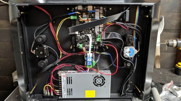
At a recent swap meet, [digitalrice] found what appeared to be a like-new QIDI X-Plus 3D printer. It wasn’t clear what was wrong with it, but considering it retails for $900 USD, he figured the asking price of $150 was worth the gamble. As you might expect, the printer ended up being broken. But armed with experience and a supply of spare parts, he was able to get this orphaned machine back up and running.

The first and most obvious problem was that the printer’s Z axis didn’t work properly. When the printer tried to home the axis, one of the motors made a terrible noise and the coupler appeared to be spinning backwards. From his experience with other printers, [digitalrice] knew that the coupler can slip on the shaft, but that didn’t appear to be the case here. Removing the stepper motor and testing it in isolation from the rest of the machine, he was able to determine it needed replacing.

Improving the printer’s filament path.

Unfortunately, the spare steppers he had weren’t actually the right size. Rather than waiting around for the proper one to come in the mail, he took an angle grinder to the stepper’s shaft and cut off the 5 mm needed to make it fit, followed by a few passes with a file to smooth out any burrs. We’re not sure we’d recommend this method of adjustment under normal circumstances, but we can’t argue with the results.

The replaced Z motor got the printer moving, but [digitalrice] wasn’t out of the woods yet. At this point, he noticed that the hotend was hopelessly clogged. Again relying on his previous experience, he was able to disassemble the extruder assembly and free the blob of misshapen PLA, leading to test prints which looked very good.

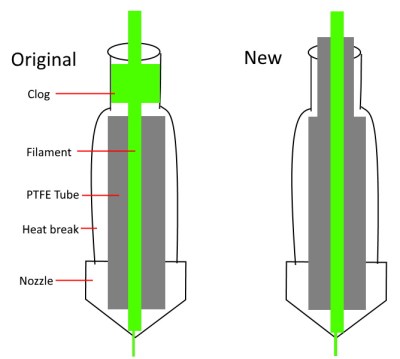
But success was short lived. After swapping to a different filament, he found it had clogged again. While clearing this second jam, he realized that the printer’s hotend seemed to have a design flaw. The PTFE tube, which is used to guide the filament down into the hotend, didn’t extend far enough out. Right where the tube ended, the filament was getting soft and jamming up the works. With a spare piece of PTFE tube and some manual reshaping, he was able to fashion a new lining which would prevent the filament from softening in this key area; resulting in a more reliable hotend than the printer had originally.

It’s great to see this printer repaired to working condition, especially since it looks like [digitalrice] was able to fix a core design flaw. But a broken 3D printer can also serve as the base for a number of other interesting projects, should you find yourself in a similar situation. For example, replacing the extruder assembly with a digital microscope can yield some very impressive results.

Hackaday Links Column Banner

Hackaday Links: September 10, 2017

Hackaday is 13! We’re going through a bit of a rebellious phase. There’s hair where there wasn’t hair before. Thirteen years ago (Sept. 5, 2004), [Phil Torrone] published the first Hackaday Post. [Phil] posted a great writeup of the history of Hackaday over on the Adafruit blog — we were saved from the AOL borg because of the word ‘hack’ — and interviewed the former and current editors of your favorite DIY website. Here’s to 13 more years and to [Phil] finding a copy of the first version of the Jolly Wrencher designed in Macromedia Flash.

Hackaday is having an unconference in the UK! Tickets for next weekend’s event went fast, but don’t worry — we’re hosting a Bring A Hack the day before.

Hurricanes are an awesome force of nature. As we learned from Harvey a week ago, livestreamed footage from the eyewall of a hurricane is fascinating. [Jeff Piotrowski] seems to be the streamer of choice. If you’re looking for something to gawk at, here you go.

Another burn is over, and I still have no idea how they moved the fuselage of a 747 from Palmdale to the playa.

You know we’re doing this whole Hackaday Prize thing where we’re giving a ton of money to people for creating cool hardware, right? We’re almost done with that. The last round of The Hackaday Prize is going on right now. The theme is anything goes, or rather there is no theme. The goal of this round is to build cool stuff. This round ends on October 16th, and yes, we’ll have the results for the Assistive Technologies round out shortly.

[Prusa] makes a lot of printers, and that means he needs to make a lot of parts to make a lot of printers. Obviously, a PTFE-cutting robot is the solution to this problem

October 5th is the Open Source Hardware Summit in Denver. Hackaday and Tindie are going, and it’s going to be a blast.  The location has moved in the last week — now it’s about half a mile away from the old venue. The speaker schedule is up, board nominations are open, and somewhere, someone is organizing a Lulzbot/Sparkfun booze cruise the day after the summit. I should be getting a van to add capacity to this trip, so if you’re interested leave a note in the comments.

An Antenna That Really Cooks–Really

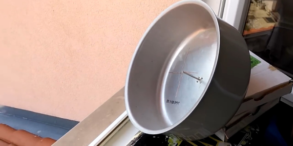
[9A4OV] set up a receiver using the HackRF board and an LNA that can receive the NOAA 19 satellite. Of course, a receiver needs an antenna, and he made one using a cooking pot. The antenna isn’t ideal – at least indoors – but it does work. He’s hoping to tweak it to get better reception. You can see videos of the antenna and the resulting reception, below.

The satellite is sending High-Resolution Picture Transmission (HRPT) data which provides a higher image quality than Automatic Picture Transmission (APT). APT is at 137 MHz, but HRPT is at 1698 MHz and typically requires a better receiver and antenna system.

Continue reading “An Antenna That Really Cooks–Really”