BNCs For An Old Instrument

Back in the summer our eye was caught by [Jazzy Jane]’s new signal generator, or perhaps we should say her new-to-her signal generator. It’s an Advance E1 from around 1950, and it was particularly interesting from here because it matches the model on the shelf above this bench. She’s back with a new video on the E1, allowing us a further look inside it as she replaces a dead capacitor, gets its audio oscillator working, and upgrades its sockets.

Treating us to a further peek inside the unit, first up is a leaky capacitor. Then a knotty question for old tech enthusiasts, to upgrade or not? The ancient co-ax connectors are out of place on a modern bench, so does originality matter enough to give it a set of BNC sockets? We’d tend to agree; just because we have some adapters for the unit here doesn’t mean it’s convenient. Following on from that is a period variable frequency audio mod which has failed, so out that comes and a little fault-finding is required to get the wiring of the audio transformer.

These instruments are not by any means compact, but they do have the advantage of being exceptionally well-built and above all cheap. We hope readers appreciate videos like the one below the break, and that you’re encouraged not to be scared of diving in to older items like this one to fix them. Meanwhile the first installment is here.

Continue reading “BNCs For An Old Instrument”

A Digital Replacement For Your Magic Eye

Magic Eye tubes were popular as tuning guides on old-school radio gear. However, the tubes, the 6U5 model in particular, have become rare and remarkably hard to come by of late. When the supply dried up, [Bjørner Sandom] decided to build a digital alternative instead.

The build relies on a small round IPS display, measuring an inch in diameter and with a resolution of 128×115 pixels. One can only presume it’s round but not perfectly so. It was then fitted with a 25mm glass lens in order to give it a richer, deeper look more akin to a real Magic Eye tube. In any case, a STM32F103CBT was selected to drive the display, with the 32-bit ARM processor running at a lovely 72 MHz for fast and smooth updates of the screen.

The screen, controller, and supporting circuitry are all built onto a pair of PCBs and installed in a 3D-printed housing that lives atop a tube base. The idea is that the build is a direct replacement for a real 6U5 tube. The STM32 controller receives the automatic gain control voltage from the radio set it’s installed in, and then drives the screen to behave as a real 6U5 tube would under those conditions.

By virtue of the smart design, smooth updates, and that nifty glass lens, the final product is quite a thing to behold. It really does look quite similar to the genuine article. If you’ve got a beloved old set with a beleagured magic eye, you might find this a project worth replicating. Video after the break.

Continue reading “A Digital Replacement For Your Magic Eye”

Making A Solid State 6AK8 Tube

[M Caldeira] had a project in mind: replacing a common vacuum tube with a solid-state equivalent. The tube in question was an EABC80 or 6AK8 triple diode triode. The key was identifying a high-voltage FET and building it, along with some other components, into a tube base to make a plug-in replacement for the tube. You can see a video about the project below.

These tubes are often used as a detector and preamplifier. Removing the detector tube from a working radio, of course, kills the audio. Replacing the tube with a single diode restores the operation of the radio, although at a disadvantage.

From there, he adds more diodes directly into the socket. Of course, diodes don’t amplify, so he had to break out a LND150 MOSFET with a limit of 500 volts across the device. It takes some additional components, and the whole thing fits in a tube base ready for the socket.

Usually, we see people go the other way using tubes instead of transistors in, say, a computer. If you want real hacking, why not make your own tubes?

Continue reading “Making A Solid State 6AK8 Tube”

Plight Of The Lowly Numitron Tube

In the 60’s and 70’s there were many ways to display numeric data. Nixie tubes, Vacuum Florescent Displays (VFD), micro projection systems, you name it. All of them had advantages and drawbacks. One of the simplest ways to display data was the RCA Numitron. [Alec] at Technology Connections has a bit of a love/hate relationship with these displays.

The Numitron is simply a seven-segment display built from light bulb filaments. The filaments run at 5 V, and by their nature are current limited.  Seven elements versus the usual ten seen in Nixie tubes reduced the number of switching elements (transistors, relays, or tubes) needed to drive them, and the single low-voltage supply was also much simpler than Nixie or even VFD systems.

Sounds perfect, right? Well, [Alec] has a bone to pick with this technology. The displays were quite dim, poorly assembled, and not very pleasing to look at. RCA didn’t bother tilting the “8” to fit the decimal point in! Even the display background was gray, causing the numbers to wash out in ambient light. Black would have been much better. In [Alec]’s words, the best way to describe the display would be “Janky,” yet he still enjoys them. In fact, he built a fancy retro-industrial-themed clock with them.

The Numitron was not a failure, though — we know variants of this display ended up in everything from gas pumps to aircraft cockpit gauges. You can even build an LED-based replica clock — no glowing filaments necessary.

Continue reading “Plight Of The Lowly Numitron Tube”

A Tube Tester Laid Bare

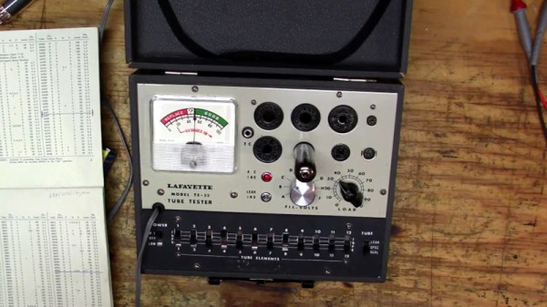
There’s still a mystique around vacuum tubes long after they were rendered obsolete by solid state devices, and many continue to experiment with them. They can be bought new, but most of us still come to them through the countless old tubes that still litter our junk boxes. But how to know whether your find is any good? [Rob’s Fixit Shop] took a look at a tube tester, once a fairly ubiquitous item, but now a rare sight.

To look at it’s a box with an array of tube sockets, a meter, and a set of switches to set the pinout for the tube under test. We expected it to use a common-cathode circuit, but instead it measures leakage between the grid and the other electrodes, a measure of how good the vacuum in the device is. In a worrying turn this instrument can deliver an electric shock, something he traces to a faulty indicator light leading to the chassis. We are however still inclined to see it as anything but safe, because the lack of mains isolation still exposes the grid to unwary fingers.

All in all though it’s an interesting introduction to an unusual instrument, and given a suitable isolating transformer we wouldn’t mind the chance to have one ourselves. If you need to test a tube and don’t have one of these, don’t worry. It’s possible to roll your own.

Continue reading “A Tube Tester Laid Bare”

A Low Voltage Tube Makes For A Handy Preamplifier

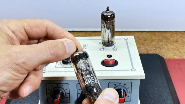
When most people think of tube circuits, the first thing that comes to mind is often the use of high-voltage power supplies. It wasn’t a given for tube circuits, though, as a range of low-voltage devices were developed for applications such as car radios. It’s one of these, an ECH83 triode-heptode, which [mircemk] has taken as the basis of an audio preamplifier circuit.

The preamp circuit is pretty simple, being a two-stage single-ended design using both halves of the tube. Between the two is a three-band tone control circuit as used in classic guitar amplifiers, making for a serviceable and easily achievable way to chase that elusive “valve sound.”

There is much discussion among audio enthusiasts about the supposed benefits of vacuum technology as opposed to transistors in an amplifier. Much of it centres around the idea that tubes distort in the even harmonics while semiconductors are supposed to do so in the odd harmonics. Still, we’d be inclined to spot a bit of snake oil instead and point to early transistor amplifiers simply being not very good compared to the tube amps of the day. That said, a well-made tube amplifier set-up will sound just as amazing as it always did, and since this one is paired with a matching power amp we wouldn’t say no to it ourselves.

If you fancy messing about with tubes for not a lot, there’s a cheap module for that.

Roll Your Own Simple Tube Tester

You can easily get carried away when trying to test things. For example, if you want to know if your car is working, you could measure the timing of the ignition and put the car on a dynamometer. Or you could just start it and figure that if it runs and moves when you put it in drive, it is probably fine.

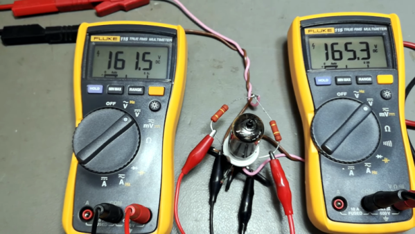
When [Thomas Scherrer] wanted to test some tubes, he made the same kind of assumption. While tubes can develop wacky failure modes, the normal difference between a working tube and a failing tube is usually not very subtle. He made a simple test rig to test tubes at DC and one operating point. Not comprehensive, but good enough most of the time. Have a look at what he did in the video below.

The tester is just a few resistors, a tube socket, and some bench power supplies. Of course, you may have to adapt it to whatever tube you are testing. If we had a lot of tubes to do, we might make the rig a bit more permanent, but for an afternoon of testing, what he has would be fine.

In addition to the power supplies, you’ll need at least one, preferably two, volt meters. He was able to validate his results with a proper tube tester. The results matched up well. While this won’t solve all your tube testing problems, it will give you a quick start.

You can build your own modern tube tester, of course. Or pick up a vintage one. Our favorite one uses punched cards.

Continue reading “Roll Your Own Simple Tube Tester”