A Brand-New Additive PCB Fab Technique?

Usually when we present a project on these pages, it’s pretty cut and dried — here’s what was done, these are the technologies used, this was the result. But sometimes we run across projects that raise far more questions than they answer, such as with this printed circuit board that’s actually printed rather than made using any of the traditional methods.

Right up front we’ll admit that this video from [Bad Obsession Motorsport] is long, and what’s more, it’s part of a lengthy series of videos that document the restoration of an Austin Mini GT-Four. We haven’t watched the entire video much less any of the others in the series, so jumping into this in the middle bears some risk. We gather that the instrument cluster in the car is in need of a tune-up, prompting our users to build a PCB to hold all the instruments and indicators. Normally that’s pretty standard stuff, but jumping to the 14:00 minute mark on the video, you’ll see that these blokes took the long way around.
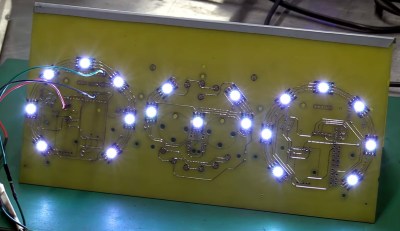
Starting with a naked sheet of FR4 substrate, they drilled out all the holes needed for their PCB layout. Most of these holes were filled with rivets of various sizes, some to accept through-hole leads, others to act as vias to the other side of the board. Fine traces of solder were then applied to the FR4 using a modified CNC mill with the hot-end and extruder of a 3D printer added to the quill. Components were soldered to the board in more or less the typical fashion.

It looks like a brilliant piece of work, but it leaves us with a few questions. We wonder about the mechanics of this; how is the solder adhering to the FR4 well enough to be stable? Especially in a high-vibration environment like a car, it seems like the traces would peel right off the board. Indeed, at one point (27:40) they easily peel the traces back to solder in some SMD LEDs.

Also, how do you solder to solder? They seem to be using a low-temp solder and a higher temperature solder, and getting right in between the melting points. We’re used to seeing solder wet into the copper traces and flow until the joint is complete, but in our experience, without the capillary action of the copper, the surface tension of the molten solder would just form a big blob. They do mention a special “no-flux 96S solder” at 24:20; could that be the secret?

We love the idea of additive PCB manufacturing, and the process is very satisfying to watch. But we’re begging for more detail. Let us know what you think, and if you know anything more about this process, in the comments below.

Continue reading “A Brand-New Additive PCB Fab Technique?”

Hacker Tactic: Building Blocks

The software and hardware worlds have overlaps, and it’s worth looking over the fence to see if there’s anything you missed. You might’ve already noticed that we hackers use PCB modules and devboards in the same way that programmers might use libraries and frameworks. You’ll find way more parallels if you think about it.

Building blocks are about belonging to a community, being able to draw from it. Sometimes it’s a community of one, but you might just find that building blocks help you reach other people easily, touching upon common elements between projects that both you and some other hacker might be planning out. With every building block, you make your or someone else’s next project quicker, and maybe you make it possible.

Sometimes, however, building blocks are about being lazy.

Continue reading “Hacker Tactic: Building Blocks”

2024 Tiny Games Contest: Neat PCB Business Card Was Inspired By The Arduboy

The humble business card is usually a small slip of cardboard with some basic contact details on it — but as hackers know, it can be so much more. [Marian] has provided us a great example in the form of his own digital business card, which doubles as a handheld game!

Wanting to make his business card more interesting for better engagement, [Marian] was inspired by the Arduboy to give it some interactivity. He chose the STM32G030F6 microcontroller as a cheap and reliable option to run his business card. He then created a 10×9 LED matrix display using Charlieplexing to minimize the amount of I/O pins required. For controls, he went with the usual directional cross plus two action buttons. He implemented a variety of games on the card—including a Flappy Bird clone and a game similar to the classic Simon toy.

Files are on GitHub for the curious. We’ve featured some other great business cards this year, too. Indeed, we ran a whole challenge! If you’re cooking up your own exemplary little PCB to hand out at conferences, don’t hesitate to let us know!

Where Do You Connect The Shield?

When it comes to polarizing and confusing questions in electronics, wiring up shields is on the top-10 list when sorted by popularity. It’s a question most of us need to figure out at some point – when you place a USB socket symbol on your schematic, where do you wire up the SHIELD and MP pins?

Once you look it up, you will find Eevblog forum threads with dozens of conflicting replies, Stackexchange posts with seven different responses plus a few downvoted ones, none of them accepted, and if you try to consult the literature, the answer will invariably be “it depends”.

I’m not a connector-ground expert, I just do a fair bit of both reading and hacking. Still, I’ve been trying to figure out this debate, for a couple years now, re-reading the forum posts each time I started a new schematic with a yet-unfamiliar connector. Now, of course, coming to this question with my own bias, here’s a summary you can fall back on.

Consumer Ports

Putting HDMI on your board? First of all, good luck. Then, consider – do you have a reason to avoid connecting the shield? If not, certainly connect the shield to ground, use jumpers if that’s what makes you comfortable, though there’s a good argument that you should just connect directly, too. The reason is simple: a fair few HDMI cables omit GND pin connections, fully relying on the shield for return currents. When your HDMI connection misfires, you don’t want to be debugging your HDMI transmitter settings when the actual No Signal problem, as unintuitive as it sounds, will be simply your shield not being grounded – like BeagleBone and Odroid didn’t in the early days. By the way, is a DVI-D to HDMI adapter not working for you? Well, it might just be that it’s built in a cheap way and doesn’t connect the shields of the two sockets together – which is fixable.

Continue reading “Where Do You Connect The Shield?”

Simple PCB Agitator Gets The Job Done

These days, PCB fab houses are just about everywhere, and you can’t go buy a taco without walking past eight of them. Still, some out there still like to etch their PCBs at home. If that sounds like you, you might see some value in [Chris Borge]’s PCB agitator. 

The design mostly relies on 3D printed parts, including the main body. It has a heavy base which is filled with concrete to keep it nicely weighed down on the table. A table for holding a PCB and fluid tank is then installed on top, via a bearing which allows it to pivot in one axis. An Arduino Nano commands the agitation of the table top, and hence the PCB etching tank, with a servo used to actually shift the table back and forth.

It’s a simple design — far simpler than some of the advanced coffee-making hardware we’ve seen recently. Regardless, it gets the job done, and done well! In testing, it accelerated [Chris]’s etching jobs significantly, we’re talking hours here. Meanwhile, if you don’t have a 3D printer on hand, you could always try building one out of junk instead!

Continue reading “Simple PCB Agitator Gets The Job Done”

Slim Tactile Switches Save Classic TI Calculator With A Bad Keypad

For vintage calculator fans, nothing strikes more fear than knowing that someday their precious and irreplaceable daily driver will become a museum piece to be looked at and admired — but never touched again. More often than not, the failure mode will be the keypad.

In an effort to recover from the inevitable, at least for 70s vintage TI calculators, [George] has come up with these nice replacement keypad PCBs. The original membrane switches on these calculators have a limited life, but luckily there are ultra-slim SMD tactile switches these days make a dandy substitute. [George] specifies a 0.8 mm thick switch that when mounted on a 1.6 mm thick PCB comes in just a hair over the original keypad’s 2.2 mm thickness. He has layouts for a TI-45, which should also fit a TI-30, and one for the larger keypads on TI-58s and TI-59s.

While these particular calculators might not in your collection, [George]’s goal is to create an open source collection of replacement keypads for all the vintage calculators sitting in desk drawers out there. And not just keypads, but battery packs, too.

It Turns Out, A PCB Makes A Nice Watch Dial

Printed circuit boards are typically only something you’d find in a digital watch. However, as [IndoorGeek] demonstrates, you can put them to wonderful use in a classical analog watch, too. They can make the perfect watch dial!

Here’s the thing. A printed circuit board is fundamentally some fiberglass coated in soldermask, some copper, maybe a layer of gold plating, and with some silk screen on top of that. As we’ve seen a million times, it’s possible to do all kinds of artistic things with PCBs; a watch dial seems almost obvious in retrospect!

[IndoorGeek] steps through using Altium Designer and AutoCAD to layout the watch face. The guide also covers the assembly of the watch face into an actual wrist watch, including the delicate placement of the movement and hands. They note that there are also opportunities to go further—such as introducing LEDs into the watch face given that it is a PCB, after all!

It’s a creative way to make a hardy and accurate watch face, and we’re surprised we haven’t seen more of this sort of thing before. That’s not to say we haven’t seen other kinds of watch hacks, though; for those, there have been many. Video after the break.

Continue reading “It Turns Out, A PCB Makes A Nice Watch Dial”