Making PCB Strip Filter Design Easy To Understand

We’ve always been fascinated by things that perform complex electronic functions merely by virtue of their shapes. Waveguides come to mind, but so do active elements like filters made from nothing but PCB traces, which is the subject of this interesting video by [FesZ].

Of course, it’s not quite that simple. A PCB is more than just copper, of course, and the properties of the substrate have to be taken into account when designing these elements. To demonstrate this, [FesZ] used an online tool to design a bandpass filter for ADSB signals. He designed two filters, one using standard FR4 substrate and the other using the more exotic PTFE.

He put both filters to the test, first on the spectrum analyzer. The center frequencies were a bit off, but he took care of that by shortening the traces slightly with a knife. The thing that really stood out to us was the difference in insertion loss between the two substrates, with the PTFE being much less lossy. The PTFE filter was also much more selective, with a tighter pass band than the FR4. PTFE was also much more thermostable than FR4, which had a larger shift in center frequency and increased loss after heating than the PTFE. [FesZ] also did a more real-world test and found that both filters did a good job damping down RF signals across the spectrum, even the tricky and pervasive FM broadcast signals that bedevil ADSB experimenters.

Although we would have liked a better explanation of design details such as via stitching and trace finish selection, we always enjoy these lessons by [FesZ]. He has a knack for explaining abstract concepts through concrete examples; anyone who can make coax stubs and cavity filters understandable has our seal of approval.

Continue reading “Making PCB Strip Filter Design Easy To Understand”

A Brand-New Additive PCB Fab Technique?

Usually when we present a project on these pages, it’s pretty cut and dried — here’s what was done, these are the technologies used, this was the result. But sometimes we run across projects that raise far more questions than they answer, such as with this printed circuit board that’s actually printed rather than made using any of the traditional methods.

Right up front we’ll admit that this video from [Bad Obsession Motorsport] is long, and what’s more, it’s part of a lengthy series of videos that document the restoration of an Austin Mini GT-Four. We haven’t watched the entire video much less any of the others in the series, so jumping into this in the middle bears some risk. We gather that the instrument cluster in the car is in need of a tune-up, prompting our users to build a PCB to hold all the instruments and indicators. Normally that’s pretty standard stuff, but jumping to the 14:00 minute mark on the video, you’ll see that these blokes took the long way around.

Starting with a naked sheet of FR4 substrate, they drilled out all the holes needed for their PCB layout. Most of these holes were filled with rivets of various sizes, some to accept through-hole leads, others to act as vias to the other side of the board. Fine traces of solder were then applied to the FR4 using a modified CNC mill with the hot-end and extruder of a 3D printer added to the quill. Components were soldered to the board in more or less the typical fashion.

It looks like a brilliant piece of work, but it leaves us with a few questions. We wonder about the mechanics of this; how is the solder adhering to the FR4 well enough to be stable? Especially in a high-vibration environment like a car, it seems like the traces would peel right off the board. Indeed, at one point (27:40) they easily peel the traces back to solder in some SMD LEDs.

Also, how do you solder to solder? They seem to be using a low-temp solder and a higher temperature solder, and getting right in between the melting points. We’re used to seeing solder wet into the copper traces and flow until the joint is complete, but in our experience, without the capillary action of the copper, the surface tension of the molten solder would just form a big blob. They do mention a special “no-flux 96S solder” at 24:20; could that be the secret?

We love the idea of additive PCB manufacturing, and the process is very satisfying to watch. But we’re begging for more detail. Let us know what you think, and if you know anything more about this process, in the comments below.

Continue reading “A Brand-New Additive PCB Fab Technique?”

Hacker Tactic: Building Blocks

The software and hardware worlds have overlaps, and it’s worth looking over the fence to see if there’s anything you missed. You might’ve already noticed that we hackers use PCB modules and devboards in the same way that programmers might use libraries and frameworks. You’ll find way more parallels if you think about it.

Building blocks are about belonging to a community, being able to draw from it. Sometimes it’s a community of one, but you might just find that building blocks help you reach other people easily, touching upon common elements between projects that both you and some other hacker might be planning out. With every building block, you make your or someone else’s next project quicker, and maybe you make it possible.

Sometimes, however, building blocks are about being lazy.

Continue reading “Hacker Tactic: Building Blocks”

Give Your SMD Components A Lift

When you are troubleshooting, it is sometimes useful to disconnect a part of your circuit to see what happens. If your new PCB isn’t perfect, you might also need to add some extra wires or components — not that any of us will ever admit to doing that, of course. When ICs were in sockets, it was easy to do that. [MrSolderFix] shows his technique for lifting pins on SMD devices in the video below.

He doesn’t use anything exotic beyond a microscope. Just flux, a simple iron, and a scalpel blade. Oh, and very steady hands. The idea is to heat the joint, gently lift the pin with the blade, and wick away excess solder. If you do it right, you’ll be able to put the pin back down where it belongs later. He makes the sensible suggestion of covering the pad with a bit of tape if you want to be sure not to accidentally short it during testing. Or, you can bend the pin all the way back if you know you won’t want to restore it to its original position.

Continue reading “Give Your SMD Components A Lift”

Your Battery Holder Is Also Your Power Switch With ToggleSlot

We really like PCB-level hacks, especially ones that show ingenuity in solving a real problem while being super cheap to implement. Hackaday.IO user [Steph] wanted a cheap way to switch a wearable on and off without having to keep popping out the battery, so they came up with a tweaked battery footprint, which is also a simple slide switch.

Most people making badges and wearables will follow the same well-trodden path of just yanking out the cell or placing some cheap switch down and swallowing the additional cost. For [Steph], the solution was obvious. By taking a standard surface-mount CR2032 button cell holder footprint, extending its courtyard vertically, and moving the negative pad up a smidge, the battery can be simply slid up to engage the pad and slid down to disengage and shut off the juice. The spring section of the positive terminal keeps enough pressure on the battery to prevent it from sliding out, but if you are worried, you can always add a dummy pad at the bottom, as well as a little solder bump to add a bit more security.

Now, why didn’t we think of this before? The KiCad footprint file can be downloaded from the project GitHub page, imported into your project and used straight away.

Many of our gadgets are powered by CR2032 cells—so many so that eliminating the need for them leads to interesting projects, like this sweet USB-powered CR2032 eliminator. But how far can you push the humble cell? Well, we held a contest a few years ago to find out!

Towards Solderless PCB Prototyping

When we think of assembling a PCB, we’re almost always thinking about solder. Whether in paste form or on the spool, hand-iron or reflow, some molten metal is usually in the cards. [Stephen Hawes] is looking for a solderless alternative for prototyping, and he shows us the progress he’s made toward going solderless in this video.

His ulterior motive? He’s the designer of the LumenPNP open-source pick-and-place machine, and is toying with the idea of a full assembly based just on this one machine. If you strapped a conductive-glue extruder head on the machine in addition to the parts placer, you’d have a full assembly in one step. But we’re getting ahead of ourselves.

[Stephen] first tries Z-tape, which is really cool stuff. Small deformable metal balls are embedded in a gel-like tape, and conduct in only the Z direction when parts are pushed down hard into the tape. But Z-tape is very expensive, requires a bit of force to work reliably, and [Stephen] finds that the circuits are intermittent. In short, Z-tape is not a good fit for the PNP machine.

But what [Stephen] does find works well is a graphite-based conductive glue. In particular, he likes the Bare Conductive paint. He tries another carbon-based paint, but it’s so runny that application is difficult, while the Bare stuff is thick and sticky. (They won’t tell you their secret formula, but it’s no secret how the stuff is basically made.) That ends up looking very promising, but it’s still pretty spendy, and [Stephen] is looking to make his own conductive paste/paint pretty soon. That’s particularly appealing, because he can control the stickiness and viscosity, and he’ll surely let us in on the secret sauce.

(We’re armchair quarterbacking here, but the addition of a small amount of methyl cellulose and xanthan gum works to turn metal powder into a formable, printable metal clay, so it might make a carbon paste similarly adjustably sticky.)

We love the end-goal here: one machine that can apply a conductive paint and then put the parts into the right place, resulting in a rough-and-ready, but completely hands-off assembly. You probably wouldn’t want to use this technique if the joint resistance was critical, or if you needed the PCB to stand up to abuse. There’s a reason that everyone in industry uses molten metal, after all. But for verifying a quick one-off, or in a rapid-prototyping environment? This would be a dream.

We’ve seen other wacky ways to go solderless before. This one uses laser-cut parts to hold the components on the PCB, for instance. And for simply joining a couple wires together, we have many more solutions, many thanks to you all in the comments!

Continue reading “Towards Solderless PCB Prototyping”

V-Cut Vias Test Your Whole Panel At Once

We might consider PCB panels as simply an intermediate step towards getting your PCBs manufactured on the scale of hundreds. This is due to, typically, an inability to run traces beyond your board – and most panel generators don’t give you the option, either. However, if you go for hand-crafted panels or modify a KiKit-created panel, you can easily add extra elements – for instance, why not add vias in the V-Cut path to preserve electrical connectivity between your boards?

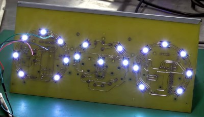
[Adam Gulyas] went out and tried just that, and it’s a wonderfully viable method. He shows us how to calculate the via size to be just right given V-Cut and drilling tolerances, and then demonstrates design of an example board with discrete component LED blinkers you can power off a coin cell. The panel gets sent off to be manufactured and assembled, but don’t break the boards apart just yet — connect power to the two through-hole testpoints on the frame, and watch your panel light up all at once.

It’s a flashy demonstration – even more so once you put light-diffusing spheres on top of the domes. You could always do such a trick with mousebites, but you risk having the tracks tear off the board, and, V-Cuts are no doubt the cleanest way to panelize – no edge cleaning is required after breaking the boards apart. Want to learn about panel design? We’ve written and featured multiple guides for you over the years.