A Homebrew Gas Chromatograph That Won’t Bust Your Budget

Chances are good that most of us will go through life without ever having to perform gas chromatography, and if we do have the occasion to do so, it’ll likely be on a professional basis using a somewhat expensive commercial instrument. That doesn’t mean you can’t roll your own gas chromatograph, though, and if you make a few compromises, it’s not even all that expensive.

At its heart, gas chromatography is pretty simple; it’s just selectively retarding the movement of a gas phase using a solid matrix and measuring the physical or chemical properties of the separated components of the gas as they pass through the system. That’s exactly what [Markus Bindhammer] has accomplished here, in about the simplest way possible. Gas chromatographs generally use a carrier gas such as helium to move the sample through the system. However, since that’s expensive stuff, [Markus] decided to use room air as the carrier.

The column itself is just a meter or so of silicone tubing packed with chromatography-grade silica gel, which is probably the most expensive thing on the BOM. It also includes an injection port homebrewed from brass compression fittings and some machined acrylic blocks. Those hold the detectors, an MQ-2 gas sensor module, and a thermal conductivity sensor fashioned from the filament of a grain-of-wheat incandescent lamp. To read the sensors and control the air pump, [Markus] employs an Arduino Uno, which unfortunately doesn’t have great resolution on its analog-to-digital converter. To fix that, he used the ubiquitous HX7111 load cell amplifier to read the output from the thermal conductivity sensor.

After purging the column and warming up the sensors, [Markus] injected a sample of lighter fuel and exported the data to Excel. The MQ-2 clearly shows two fractions coming off the column, which makes sense for the mix of propane and butane in the lighter fuel. You can also see two peaks in the thermal conductivity data from a different fuel containing only butane, corresponding to the two different isomers of the four-carbon alkane.

[Markus] has been on a bit of a tear lately; just last week, we featured his photochromic memristor and, before that, his all-in-one electrochemistry lab.

Continue reading “A Homebrew Gas Chromatograph That Won’t Bust Your Budget”

A Brief Look Inside A Homebrew Digital Sampler From 1979

While we generally prefer to bring our readers as much information about a project as possible, sometimes we just have to go with what we see. That generally happens with new projects and work in progress, but it can also happen with old projects. Sometimes very old indeed, as is the case with this digital sampling unit for analog oscilloscopes, circa 1979.

We’ve got precious little to go on with this one other than the bit of eye candy in the video tour below and its description. Luckily, we’ve had a few private conversations with its maker, [Mitsuru Yamada], over the years, enough to piece together a little of the back story here — with apologies for any wrong assumptions, of course.

Built when he was only 19, this sampler was an attempt to build something that couldn’t be bought, at least not for a reasonable price. With no inexpensive monolithic analog-to-digital converters on the market, he decided to roll his own. A few years back he recreated the core of that with his all-discrete successive approximation ADC.

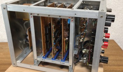
The sampler shown below has an 8-bit SAR ADC using discrete CMOS logic and enough NMOS memory to store 256 samples. You can see the ADC and memory cards in the homebrew card cage made from aluminum angle stock. The front panel has a ton of controls and sports a wide-range attenuator, DC offset, and trigger circuit with both manual and automatic settings.

It’s an impressive build, especially for a 19-year-old with presumably limited resources. We’ve reached out to [Yamada-san] in the hope that he’ll be able to provide more details on what’s under the hood and if this still works after all these years. We’ll pass along whatever we get, but in the meantime, enjoy.

Continue reading “A Brief Look Inside A Homebrew Digital Sampler From 1979”

Arduino Measures Remaining Battery Power With Zero Components, No I/O Pin

[Trent M. Wyatt]’s CPUVolt library provides a fast way to measure voltage using no external components, and no I/O pin. It only applies to certain microcontrollers, but he provides example Arduino code showing how handy this can be for battery-powered projects.

The usual way to measure VCC is simple, but has shortcomings.

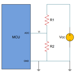
The classical way to measure a system’s voltage is to connect one of your MCU’s ADC pins to a voltage divider made from a couple resistors. A simple calculation yields a reading of the system’s voltage, but this approach has two disadvantages: one is that it constantly consumes power, and the other is that it ties up a pin that you might want to use for something else.

There are ways to mitigate these issues, but it would be best to avoid them entirely. Microchip application note 2447 describes a method of doing exactly that, and that’s precisely what [Trent]’s Arduino library implements.

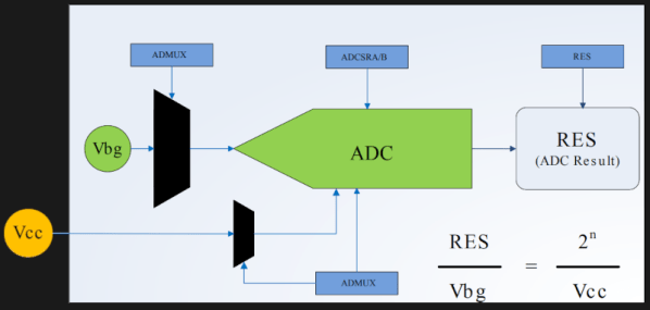
What happens in this method is one selects Vbg (a fixed internal voltage reference that is temperature-independent) as Vin, and selects Vcc as the ADC’s voltage reference. This is essentially backwards from how the ADC is normally used, but it requires no external hookup and is only a bit of calculation away from determining Vcc in millivolts. There is some non-linearity in the results, but for the purposes of measuring battery power in a system or deciding when to send a “low battery” signal, it’s an attractive solution.

Being an Arduino library, CPUVolt makes this idea very easy to use, but the concept and method is actually something we have seen before. If you’re interested in the low-level details, then check out our earlier coverage which goes into some detail on exactly what is going on, using an ATtiny84.

Upgraded Toy Guitar Plays Music

Getting the finishing details on a Halloween costume completed is the key to impressing friends and strangers alike on the trick-or-treat rounds. Especially when it comes to things like props, these details can push a good Halloween costume to great with the right touches. [Jonathan]’s friend’s daughter will be well ahead of the game thanks to these additions to a toy guitar which is part of her costume this year.

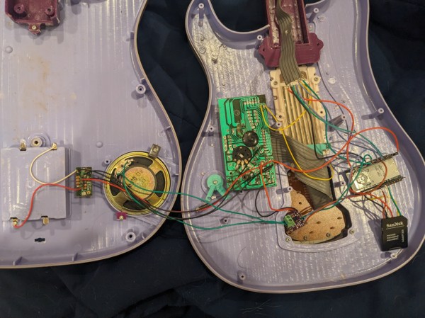
The toy guitar as it was when it arrived had the capability to play a few lackluster sound effects. The goal here was to get it to play a much more impressive set of songs instead, and to make a couple upgrades along the way as well. To that end, [Jonathan] started by dismantling the toy and investigating the PCBs for potential reuse. He decided to keep the buttons in the neck of the guitar despite their non-standard wiring configuration, but toss out the main board in favor of an ESP32. The ESP32 is tasked with reading the buttons, playing a corresponding song loaded on an SD card, and handling the digital to analog conversion when sending it out to be played on the speaker.

The project doesn’t stop there, though. [Jonathan] also did some custom mixing for the songs to account for the lack of stereo sound and a working volume knob, plus he used the ESP32’s wireless capabilities to set the guitar up as a local file server so that songs can be sent to and from the device without any wires. He also released the source code on the project’s GitHub page for anyone looking to use any parts of this project. Don’t forget there’s a Halloween contest going on right now, so be sure to submit the final version of projects like these there!

Continue reading “Upgraded Toy Guitar Plays Music”

Guitar Distortion With Diodes In Code, Not Hardware

Guitarists will do just about anything to get just the right sound out of their setup, including purposely introducing all manner of distortion into the signal. It seems counter-intuitive, but it works, at least when it’s done right. But what exactly is going on with the signal? And is there a way to simulate it? Of course there is, and all it takes is a little math and some Arduino code.

Now, there are a lot of different techniques for modifying the signal from an electric guitar, but perhaps the simplest is the humble diode clipping circuit. It just uses an op-amp with antiparallel diodes either in series in the feedback loop or shunting the output to ground. The diodes clip the tops and bottoms off of the sine waves, turning them into something closer to a square wave, adding those extra harmonics that really fatten the sound. It’s a simple hack that’s easy to implement in hardware, enough so that distortion pedals galore are commercially available.

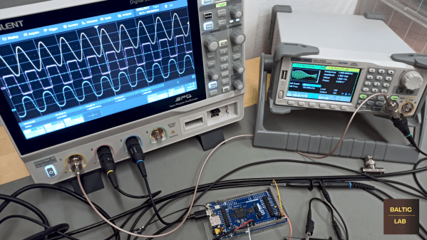
In the video below, [Sebastian] explains that this distortion is also pretty easy to reproduce algorithmically. He breaks down the math behind this, which is actually pretty approachable — a step function with a linear part, a quadratic section, and a hard-clipping function. He also derives a second, natural exponent step function from the Schockley diode equation that is less computationally demanding. To implement these models, [Sebastian] chose an Arduino GIGA R1 WiFi, using an ADC to digitize the guitar signal and devoting a DAC to each of the two algorithms. Each distortion effect has its own charms; we prefer the harsher step function over the exponential algorithm, but different strokes.

Kudos to [Sebastian] for this easy-to-understand treatment of what could otherwise be a difficult subject to digest. We didn’t really expect that a guitar distortion pedal would lead down the rabbit hole to diode theory and digital signal processing, but we’re glad it did.

Continue reading “Guitar Distortion With Diodes In Code, Not Hardware”

STM32 Oscilloscope Uses All The Features

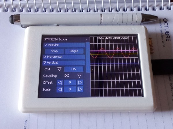
[jgpeiro] is no slouch when it comes to building small, affordable oscilloscopes out of common microcontrollers. His most recent, based on an RP2040 with two channels that ran at 100 MSps, put it on the order of plenty of commercially-available oscilloscopes at this sample rate but at a fraction of the price. He wanted to improve on the design though, making a smaller unit with a greatly reduced bill-of-materials and with a more streamlined design, so he came up with this STM32-based oscilloscope.

The goal of this project was to base as many of the functions around the built-in capabilities of the STM32 as possible, so in addition to the four input channels and two output channels running at 1 MHz, the microcontroller also drives a TFT display which has been limited to 20 frames per second to save processor power for other tasks. The microcontroller also has a number of built-in operational amplifiers which are used as programmable gain amplifiers, further reducing the amount of support circuitry needed on the PCB while at the same time greatly improving the scope’s capabilities.

In fact, the only parts of consequence outside of the STM32, the power supply, and the screen are the inclusion of two operational amplifiers included to protect the input channels from overvoltage events. It’s an impressive build in a small form factor, and we’d say the design goal of keeping the parts count low has been met as well. If you do need something a little faster though, his RP2040-based oscilloscope is definitely worth checking out.

Continue reading “STM32 Oscilloscope Uses All The Features”

A High Precision ADC That You Can Understand!

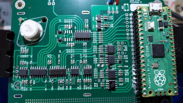
In a world where an analogue to digital converter is all too often an integrated peripheral buried inside a microcontroller, it’s easy to forget how simple these devices can be when built from first principles. An entry in our Op-Amp Challenge from [NNNI] demonstrates this perfectly, it’s a high resolution multi-slope ADC for instrumentation purposes, constructed using a mixture of op-amps, logic chips, and a Raspberry Pi Pico. Best of all, it’s easy to understand, so there’s little of that analogue mystique to worry about.

This type of ADC measures an analogue value by counting how long it takes to charge a capacitor to that voltage. A simple version that measures charge time has a few drawbacks, so this project goes from single slope to multi slope by measuring both charge and discharge times compared to the voltage. Pay attention to component matching and reference stability, and such a design can offer a very high resolution measurement.

The value in this project lies not only in the design itself, but also in the extremely comprehensive description of its operation, which should teach most readers a thing or two. That curvy-line PCB is rather nice, too. We used single slope ADCs to read analogue joysticks back in the day, but we certainly learned something here. Want to see another? This isn’t the first dual slope ADC we’ve seen.