Measuring temperature turns out to be a fundamental function for a huge number of devices. You furnace’s programmable thermostat and digital clocks are obvious examples. If you just needed to know if a certain temperature is exceeded, you could use a bimetalic coil and a microswitch (or a mercury switch as was the method with old thermostats). But these days we want precision over a range of readings, so there are thermocouples that generate a small voltage, RTDs that change resistance with temperature, thermistors that also change resistance with temperature, infrared sensors, and vibrating wire sensors. The bandgap voltage of a semiconductor junction varies with temperature and that’s predictable and measurable, too. There are probably other methods too, some of which are probably pretty creative.

The point is, there are plenty of ways to measure anything, but in every case, you are converting what you want to know (temperature) into something you know how to measure like voltage, current, or physical position. Let’s take a look at how some of the most interesting temperature sensors accomplish this.
Thermocouples
Thermocouples take advantage of something called the Seebeck effect. When two dissimilar metals form a junction and experience a temperature gradient, an electric potential forms. The key is that it is a gradient in temperature that makes the device work. Thermocouples have a hot junction and a cold junction. If you want to measure temperature, you need a reference junction. As an aside, the effect works in reverse — the Peltier effect — where passing current through a pair of junctions makes one side hot and the other one cold.
In the old days, you’d plunge the cold junction into a bucket of ice. Today, it is more likely that you’ll use another method to get the temperature of the cold junction and then compensate. There are chips that will do that for you, of course.
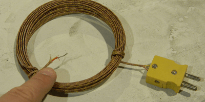
The downside is that the temperature reading is not linear. You’ll see different types of thermocouples and each type uses two different wire materials. The type tells you what calibration curve to use and, of course, you select the metal for the application you need. For example, a type J uses iron as one of the two wires and a type T uses copper.
The only other big consideration is how you run wires to the thermocouple. Since the device operates on a junction between two different types of wires, you have to be careful how you connect other wires to the device. Want to know more? [Bil Herd] did a deep dive into how to build a thermocouple amplifier.
Thermocouples that measure infrared from a distance are known as thermopiles. These are common in non-contact thermometers and passive IR (PIR) sensors. A PIR sensor detects the difference in temperature between two sensors and infers that something has changed in the field of view.
Resistance Devices
There are several different types of material that can exhibit temperature changes with resistance. The biggest factor is if the device has a positive or negative temperature coefficient. In other words, does the resistance go up or down in response to a change in temperature?
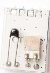
Thermistors are slightly different in construction from resistance temperature detectors, or RTDs. Usually, thermistors have less hysteresis and self-heating problems than the metal-based (often platinum) RTDs. However, in either case, you’ll have to measure resistance and fit it to a curve to get the real temperature.
Reading thermistors is a very common operation and there are a lot of tricks people have developed over the years. You can also spend math processing to get better curve fits, or do simple math and get less accuracy.
Semiconductor Junctions and Accidental Sensors
The bandgap voltage of semiconductor material varies predictably with temperature. If you ever get deep into solid state design, you’ll see the T term in the diode equation and all its manifestations. It is no surprise, then, that a lot of ICs use this property for sensing temperature.
Some chips are made to be temperature sensors. For example, the common LM34 and LM35 chips exploit this property with some additional circuits to provide a nice 10mV per degree (the LM34 measures Farhenheit and the LM35 measures Celcius). That makes them very easy to use.
Some chips, like the CPU in your PC, use the same method to measure internal temperature for reporting and thermal management. However, there are other ways non-temperature sensor ICs can measure temperature.
It turns out, almost all of our circuits are sensitive to temperature in some way. Measuring the internal clock of a CPU against an external reference can show temperature-induced changes.
Oddball Sensors
There are a multitude of other ways to measure temperature. For example, a vibrating wire sensor uses what amounts to a guitar string. The measurement involves exciting the string and detecting the frequency of vibration. As the supporting structure shrinks and expands with temperature changes, the tone of the string changes.
You can get an approximate temperature in degrees Fahrenheit by counting the number of chirps crickets make. Count the number of chirps in 15 seconds and then add 37. It wouldn’t surprise me if someone’s done that in some obscure instrument. [Kevin] in Terre Haute says the number is 40 in the video below, and not 37, but I guess it isn’t an exact science.
Of course, an increasingly common way to measure temperature is to use some form of smart sensor. A module or IC can use any of the methods we’ve talked about, convert it to engineering units, and send the data over something like an I2C bus. This is a level abstraction, but you still ought to understand the underlying benefits and limitations involved with the sensor you want to use.
While there may be more, there aren’t any other common techniques for measuring temperature. But there are still lots of sensors left to talk about in future articles.

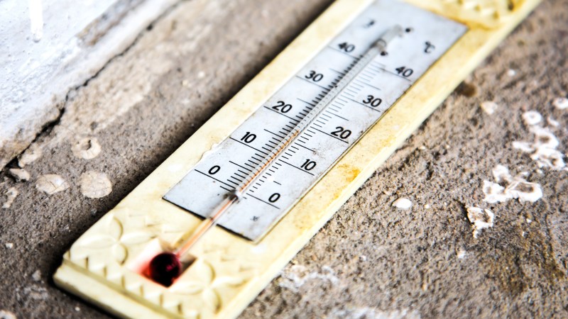




i made a light to permanently mount on my bike, and i wanted to put a simple charge-state sensor using just a few transistors. i’m pretty novice at this so i was very proud of the 2-transistor circuit i devised.
when power is first applied, an NPN controlled by a voltage-divider (at less than the nominal gate voltage, so it was only conducting microamps and its response to small voltage changes was exponential) charges a capacitor. and until that capacitor reaches a certain level of charge, an FET is on, lighting an LED. it was set up so that if the battery was fully charged (4.2V), it would take less than 1s to turn off the light. but if the battery was fully discharged (3.6V), it would take about 10s to turn off the light.
obviously, it’s a thermometer. in the summer, the light flashes too quick to notice and in the winter it runs for 5 seconds even if it’s freshly charged.
i kind of anticipated that but my back of the envelope calculations underestimated the effect, obviously.
I used the effect to regulate current of my bike’s headlight so that it gives more current at cold temperatures (winter) and less current in the warm (summer).
In the spirit of hacking, I came up with this,
Take a long brewing thermometer, stick it to a linear sensor from a flat bed scanner, say 1200 dpi. Add some smd LEDs and a few strips of LCD tv diffuser sheet.
Heat shrink it all together and you have a really high precision temperature sensor with no moving parts, all be it perhaps slightly bulky.
Wax motors might be one of my favourites.
Previously covered here on HaD if I recall.
I read an interesting, if sparse note a few weeks back, the subject in question, wax motors being a used to generate electricity for submarines.
It begs the question, perhaps the day night cycle of more land based or even orbital temperature fluctuations could also be utilised. If it could be scaled up to something with the surface area of a football pitch, perhaps by way of multiple stacked layers, it could provide an interesting alternative to solar energy.
Monsieur Carnot would like to have a word with you.
That’s satisfyingly clever.
Anywhere there’s details? Photos?
Make a project under hackaday?
I haven’t made it. I just thought of it on the spot. Although to be honest, if someone built that and posted it, it’s the sort of thing I’d definitely read on here.
Terre Haute, Indiana is spelled with an ‘e’. Nice place, I grew up there.
Got it, thanks!
And Celcius is actually Celsius. Or maybe you misspelled Farhenheit :)
Other solutions:
Put the barometer on a long string, swing from the top of the building and time the pendulum period.
Put the barometer on the ground, measure its height and the height of its shadow. Measure the building’s shadow and use similar triangles to calculate.
Stand on top of tower, smack barometer with a stick and time the echo return.
Or drop the barometer and time it hitting the ground…
The MAX6577 is kind of neat: it outputs frequency proportional to absolute temperature. 300 Hz = 300 K (=27 C). You can have arbitrarily fine precision: just count longer. Expensive ($2) from legit sources, but cheap from the usual suspects.
Arbitrary precision, but terrible accuracy. The datasheet says +/-3C at room temperature, and it only gets worse from there. You can probably try to calibrate it, but then why bother, just use an mcu and a better temperature sensor.
Methinks the mentioned components are used to directly measure temperature, not ‘heat’. Granted, transfer of energy can be derived by some temperature data.
I know, pedantic. But ‘hacking’ is applied physics.
Came here to say that. Thank you.
I have a solar hot water preheater that I built … um, maybe 25 years ago. I needed a couple temp sensors to compare the collector temp to the tank temp and turn on the pump when the former exceeded the latter. Being frugal, I used 1N4148 diodes which are very very cheap. The problem is that the forward voltage only changes 2 millivolts per degree Canadian. Not much. So I strung 5 in series and got 10 millivolts/deg at a nice 3 volt level.
Another nice way to measure temperature: based on the temperature-dependent thermal diffusivity of silicon (i.e. the rate at which heat spreads through the material):
https://ieeexplore.ieee.org/abstract/document/5433900/
Super accurate temperature sensors are made using this. Could distinguish a carton of spoiled milk from an unspoiled one by the slight difference in temperature due to the growing bacteria and the heat they produce.
Diode temperature sensors work pretty well. And plain-old microcontroller ADCs can get you within a degree or so easily enough.
https://hackaday.com/2018/04/16/two-cent-temperature-sensors/
Putting them in series is a nice trick.
“Thermocouples that measure infrared from a distance are known as thermopiles.” This is not exactly accurate. Wikipedia offers a better explanation, but a thermopile is like a “pile” of thermocouples. When connected in series these allow to amplify the reading of a temperature difference between two sides of the device. This is in turn used in non-contact thermometers where one side is heated/cooled by the IR radiation from/to the measured object and the other side is stuck to a NTC.
Engineering rule of thumb
“every sensor is also a temperature sensor”.
Many employ elaborate means to remove this feature.
Nothing about the acoustic thermometer made by late Jim Williams?
AN131 – An Introduction to Acoustic Thermometry
https://www.analog.com/media/en/technical-documentation/application-notes/an131f.pdf